Toyota Sienna Service Manual: Air Intake Control Circuit
DESCRIPTION
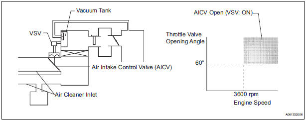
The air cleaner is equipped with two inlets, one of which is opened or closed by the Air Intake Control Valve (AICV). This system reduces intake noise and increases engine power at low-to-high engine speed range.
When the engine is operating in the low-to-mid speed range, this control operates the AICV to close one of the air cleaner inlets. When the engine speed is more than 3600 rpm and the opening angle of the throttle valve is more than 60, the ECM activates the VSV and opens the AICV.
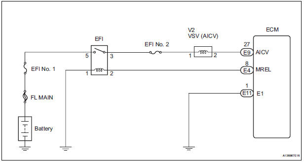
WIRING DIAGRAM
INSPECTION PROCEDURE
1 PERFORM ACTIVE TEST BY INTELLIGENT TESTER (VSV FOR AICV)
- Turn the ignition switch to the ON position and turn the intelligent tester on.
- Select the following menu items: DIAGNOSIS / ENHANCED OBD II / ACTIVE TEST / INTAKE CTL VSV1 and operate the VSV for AICV.
- Check the operation of the VSV when the VSV is operated by the intelligent tester.
Standard
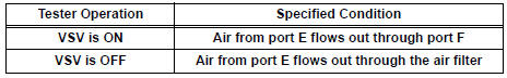
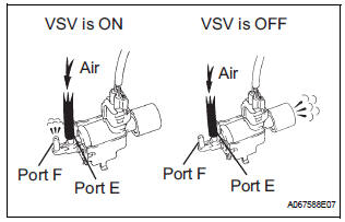
2 CHECK VSV (FOR AICV)
- Inspect the intake air control valve assembly
3 CHECK HARNESS AND CONNECTOR (VSV FOR AICV - ECM)
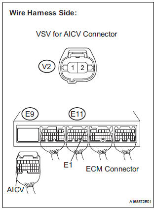
- Check the wire harness between the VSV for AICV connector and the ECM connector.
- Disconnect the V2 VSV for AICV connector.
- Disconnect the E9 ECM connector.
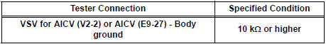
- Measure the resistance according to the value(s) in the table below.
Standard resistance: Check for open
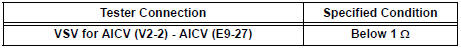
Check for short
- Reconnect the ECM connector
4 INSPECT FUSE (EFI NO. 2 FUSE)

- Check the EFI No. 2 fuse.
- Remove the EFI No. 2 fuse from the engine room junction block.
- Measure the EFI No. 2 fuse resistance.
Standard resistance: Below 1 Ω
- Reinstall the EFI No. 2 fuse.
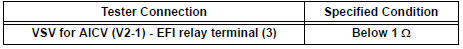
5 CHECK HARNESS AND CONNECTOR (VSV FOR AICV - EFI RELAY)
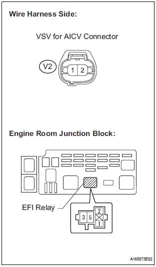
- Check the wire harness between the VSV for AICV and the EFI relay.
- Remove the EFI relay from the engine room junction block.
- Measure the resistance according to the value(s) in the table below.
Standard resistance : Check for open
- Reconnect the VSV for AICV connector.
- Reinstall the EFI relay.
6 INSPECT VACUUM TANK
- Inspect the vacuum tank
CHECK ECM POWER SOURCE CIRCUIT
 ACIS Control Circuit
DESCRIPTION
This circuit opens and closes the Intake Air Control Valve (IACV) in response
to changes in the engine
load in order to increase the intake efficiency (ACIS: Acoustic Control
Inducti ...
 MIL Circuit
DESCRIPTION
The MIL (Malfunction Indicator Lamp) is used to indicate vehicle malfunctions
detected by the ECM.
When the ignition switch is turned to the ON position, power is supplied to the
M ...
Other materials:
Removal
HINT:
Remove the RH side by the same procedure as the LH side.
1. REMOVE REAR WHEEL
2. DRAIN BRAKE FLUID
NOTICE:
Wash the brake fluid off immediately if it attaches to
any painted surface.
3. SEPARATE REAR BRAKE TUBE NO.4
(a) Remove the clip and a disconnect, the rear brake
flexible hos ...
Heated oxygen sensor (for 2wd)
Components
Removal
1. DISCONNECT CABLE FROM NEGATIVE BATTERY
TERMINAL
CAUTION:
Wait at least 90 seconds after disconnecting the
cable from the nagative (-) battery terminal to
prevent airbag and seat belt pretensioner activation.
2. REMOVE HEATED OXYGEN SENSOR (for Bank ...
Open in Side Squib LH Circuit
DTC B0116/48 Open in Side Squib LH Circuit
DESCRIPTION
The side squib LH circuit consists of the center airbag sensor assembly and
the front seat side assembly
LH.
This circuit instructs the SRS to deploy when deployment conditions are met.
DTC B0116/48 is recorded when an open circuit is ...
