Toyota Sienna Service Manual: Engine Immobiliser System Malfunction
DTC B2799 Engine Immobiliser System Malfunction
DESCRIPTION
This DTC is output when the ECM detects errors in communication between the transponder key ECU and the ECM, or in the communication lines. This DTC is also output when an engine start is attempted while the ECU communication ID between the transponder key ECU and the ECM are different. Before troubleshooting for this DTC, make sure that there is no DTC detected in the transponder key ECU. If there is key code-related DTC detected in the transponder key ECU, repair it first.
|
DTC No. |
DTC Detection Condition |
Trouble Area |
|
B2799 |
|
|
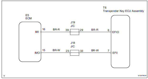
WIRING DIAGRAM
INSPECTION PROCEDURE
1 CHECK HARNESS AND CONNECTOR (TRANSPONDER KEY ECU ASSEMBLY - ECM)
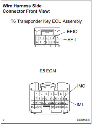
- Disconnect the T6 ECU and E5 ECM connectors.
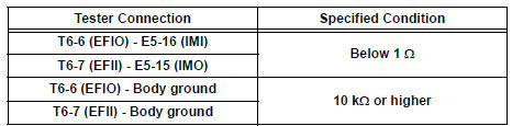
- Check the resistance of the wire harness side connectors.
Resistance
2 CHECK TRANSPONDER KEY ECU ASSEMBLY
- After replacing the transponder key ECU assembly with a normally functioning transponder key ECU assembly, check that the engine starts.
OK: The engine starts
END
 No Communication in Immobiliser System
DTC B2796 No Communication in Immobiliser System
DTC B2798 Communication Malfunction No. 2
DESCRIPTION
These codes are stored in the memory when a key that does not have a
transponder chip is ins ...
 Cruise control
...
Other materials:
Removal
1. PRECAUTION
HINT:
See page RS-1
2. DISCONNECT BATTERY NEGATIVE TERMINAL
Wait for 90 seconds after disconnecting the battery
terminal to prevent the airbag working.
3. PLACE FRONT WHEELS FACING STRAIGHT AHEAD
4. REMOVE STEERING WHEEL COVER LOWER NO.2
(See page RS-424)
5. REMOVE STEERING WH ...
Diagnostic trouble code chart
HINT:
If a trouble code is displayed during the DTC check, check
the circuit indicated by the DTC. For details of each code,
turn to the page for the respective DTC Code. in the DTC
chart.
Inspect the fuse and relay before investigating the trouble
areas as shown in the table below.
...
Power Slide Door RH does not Operate When Using Inside / Outside
Handle
DESCRIPTION
The inside / outside handles have the ability to control operation
of the power slide door. Pulling either
handle transmits a request signal to the power slide door ECU RH, which then
commands the power
slide door control motor and clutch to open / close the power sli ...
