Toyota Sienna Service Manual: On-vehicle inspection
1. CONNECT INTELLIGENT TESTER
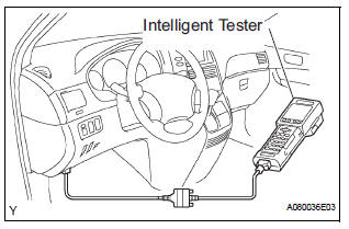
(a) Connect the intelligent tester to the DLC3.
(b) Start the engine and run at idle.
(c) Select the ACTIVE TEST mode on the intelligent tester.
HINT: Please refer to the intelligent tester operator's manual for further details.
2. INSPECT ACTUATOR MOTOR OPERATION
(a) With the motor relay on, check the actuator motor operation noise.
(b) Turn the motor relay off.
(c) Depress the brake pedal and hold it for approximately 15 seconds. Check that the brake pedal cannot be depressed.
(d) With the motor relay on, check that the pedal does not pulsate.
NOTICE: Do not keep the motor relay turned on for more than 5 seconds continuously. When operating it continuously, set an interval of more than 20 seconds.
(e) Turn the motor relay off and release the brake pedal.
3. INSPECT RIGHT FRONT WHEEL OPERATION
NOTICE: Never turn on the solenoids in a manner different to those described below.
(a) With the brake pedal depressed, perform the following operations.
(b) Turn the SFRH and SFRR solenoids on simultaneously, and check that the pedal cannot be depressed.
NOTICE: Do not keep the solenoid turned on for more than 10 seconds continuously. When operating it continuously, set an interval of more than 20 seconds.
(c) Turn the SFRH and SFRR solenoids off simultaneously, and check that the pedal can be depressed.
(d) Turn the motor relay on, and check that the pedal returns.
NOTICE: Do not keep the motor relay turned on for more than 5 seconds continuously. When operating it continuously, set an interval of more than 20 seconds.
(e) Turn the motor relay off and release the brake pedal.
4. INSPECT OTHER WHEEL OPERATION
(a) Using the same procedure, check the solenoids of the other wheels.
HINT: Left front wheel: SFLH, SFLR Right rear wheel: SRRH, SRRR Left rear wheel: SRLH, SRLR
 Brake actuator (w/ vsc)
Components
...
 Removal
1. DRAIN BRAKE FLUID
NOTICE:
Wash brake fluid off immediately if it adheres to any
painted surface.
2. DISCONNECT BATTERY NEGATIVE TERMINAL
3. REMOVE AIR CLEANER ASSEMBLY WITH HOSE
4. REMOVE BRA ...
Other materials:
Diagnosis system
1. DIAGNOSIS FUNCTION
The diagnosis function makes the light and the
multi-information display come on, and the CRUISE
main indicator light blink as shown in the illustration.
When a malfunction occurs in the dynamic laser
cruise control system, the DTCs are stored in the
ECM ...
Mechanical system tests
1. PERFORM MECHANICAL SYSTEM TESTS
(a) Measure the stall speed.
The object of this test is to check the overall
performance of the transaxle and engine by
measuring the stall speeds in the D position.
NOTICE:
Driving test should be done on a paved road
(a nonskid road).
Per ...
Diagnostic trouble code chart
If a trouble code is displayed during the DTCs check (sensor
check), check the circuit listed for the code in the table below
(Proceed to the page given for that circuit).
AIR CONDITIONING SYSTEM
HINT:
*1: If the cabin temperature is approximately -18.6°C (-
3.7°F) or lo ...
