Toyota Sienna Service Manual: Reclining Motor Circuit
DESCRIPTION
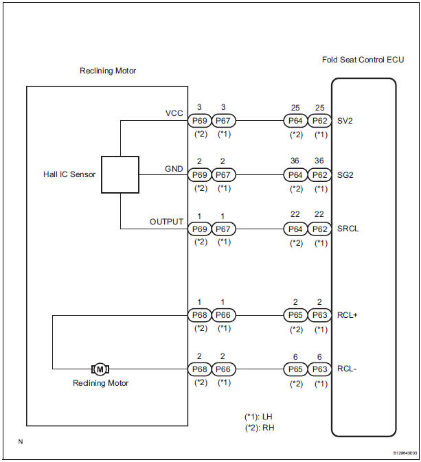
The fold seat control ECU receives a switch operation signal from the power rear no. 2 seat switch and the fold seat switch, and activates the reclining motor. At this time, the Hall IC (seatback position sensor) detects the actuation of the seatback and sends a seatback actuation signal to the fold seat control ECU.
The fold seat control ECU uses signals from the Hall IC (seatback position sensor) to detect if an object is caught or if any other abnormal condition has occurred.
WIRING DIAGRAM
INSPECTION PROCEDURE
1 INSPECT FOLD SEAT CONTROL ECU
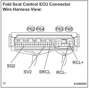
- Remove the fold seat control ECU with connectors still connected.
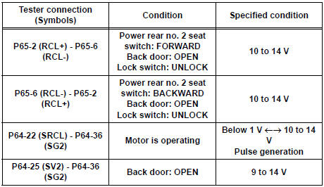
- Measure the voltage according to the value(s) in the table below.
Standard voltage: LH side
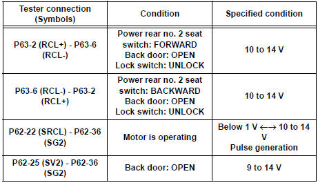
RH side
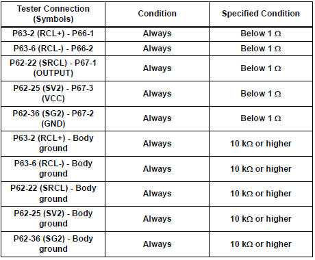
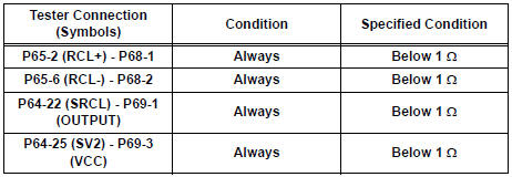
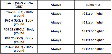
2 CHECK HARNESS AND CONNECTOR (FOLD SEAT CONTROL ECU - RECLINING MOTOR)
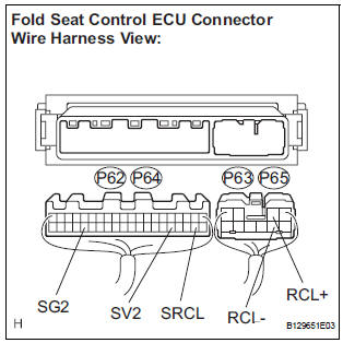
- Disconnect the connectors from the fold seat control ECU.
- Disconnect the connectors from the reclining motor.
- Measure the resistance according to the value(s) in the table below.
Standard resistance: LH side
RH side
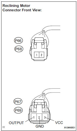
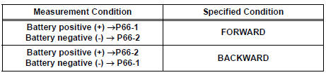
3 INSPECT RECLINING MOTOR
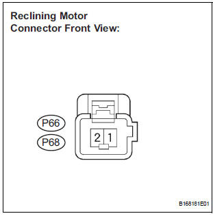
- Check reclining motor operation.
- Check if the motor rotates smoothly when the battery is connected to the reclining motor.
OK: LH side
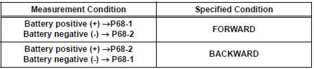
RH side
REPLACE FOLD SEAT CONTROL ECU
 Folding Motor Circuit
DESCRIPTION
The fold seat control ECU receives a switch operation signal from the fold
seat switch and activates the
folding motor. At this time, the Hall IC (seat cushion position sensor) detects ...
 Release Actuator Circuit
DESCRIPTION
The fold seat control ECU receives a switch operation signal from the fold
seat switch and activates the
release actuator. The release actuator releases the lock of the stowed seat
b ...
Other materials:
Short to GND in Front Passenger Side Squib
Circuit
DTC B0107/51 Short to GND in Front Passenger Side Squib
Circuit
DESCRIPTION
The front passenger side squib circuit consists of the center airbag sensor
assembly and the front
passenger airbag assembly.
The circuit instructs the SRS to deploy when deployment conditions are met.
DTC B0107/ ...
Identification information
VEHICLE IDENTIFICATION AND SERIAL NUMBERS
1. VEHICLE IDENTIFICATION NUMBER
(a) The vehicle identification number is stamped on the
vehicle identification number plate and the
certification label, as shown in the illustration.
A:
Vehicle Identification Number Plate
B:
...
Front Occupant Classification Sensor RH Collision
Detection
DTC B1786 Front Occupant Classification Sensor RH Collision
Detection
DESCRIPTION
DTC B1786 is output when the occupant classification ECU receives a collision
detection signal sent by
the front occupant classification sensor RH if an accident occurs.
DTC B1786 is also output when the front ...
