Toyota Sienna Service Manual: On-vehicle inspection
1. INSPECT BRAKE PEDAL HEIGHT
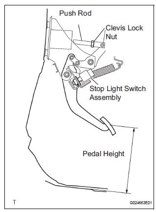
(a) Check the brake pedal height.
Pedal height from dash panel: 150.3 to 160.3 mm (5.917 to 6.311 in.)
NOTICE: Do not adjust the pedal height. Doing so by changing the push rod length will structurally change the pedal ratio.
2. CHECK AND ADJUST STOP LIGHT SWITCH
(a) Disconnect the stop light switch assembly connector from the stop light switch assembly.
(b) Turn the stop light switch assembly counterclockwise and remove the stop light switch assembly.
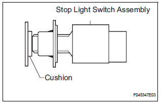
(c) Insert the stop light switch assembly until the body hits the cushion.
NOTICE: When inserting the stop light switch assembly, support the pedal from behind so that the pedal is not pushed in.
(d) Make a quarter turn clockwise to install the stop light switch assembly.
NOTICE:
- When inserting the stop light switch assembly, support the pedal from behind so that the pedal is not pushed in.
- The turning torque for installing the stop light switch assembly
Torque: 1.5 N*m (15 kgf*cm, 13 in.*lbf) or less
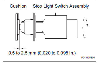
(e) Connect the stop light switch connector to the stop light switch assembly.
(f) Check the protrusion of the rod.
Protrusion of the rod: 0.5 to 2.5mm (0.020 to 0.098 in.)
3. CHECK PEDAL FREE PLAY
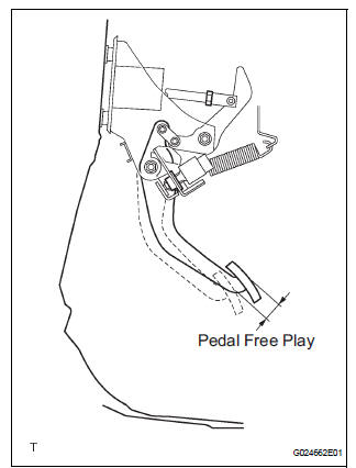
(a) Stop the engine and depress the brake pedal several times until there is no more vacuum left in the booster.
(b) Push in the pedal until the beginning of the resistance is felt. Measure the distance, as shown.
Pedal free play: 1 to 6 mm (0.04 to 0.24 in.)
4. CHECK PEDAL RESERVE DISTANCE
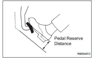
(a) Release the parking brake pedal.
With the engine running, depress the pedal and measure the pedal reserve distance, as shown.
Pedal reserve distance from asphalt sheet at 490 N (50 kgf, 110 lbf): More than 52 mm (2.0 in.)
HINT: If the distance is out of the specification, troubleshoot the brake system.
 Brake pedal
Components
...
 Removal
1. SEPARATE BATTERY NEGATIVE TERMINAL
2. REMOVE FRONT DOOR SCUFF PLATE LH
3. REMOVE COWL SIDE TRIM BOARD LH
4. REMOVE INSTRUMENT PANEL FINISH PANEL SUBASSEMBLY
LOWER LH
(a) Remove the 2 bolts and ...
Other materials:
Removal
1. REMOVE INSTRUMENT CLUSTER CENTER NO. 1 FINISH PANEL
2. REMOVE INSTRUMENT CLUSTER CENTER NO. 2
FINISH PANEL
3. REMOVE SHIFT LEVER KNOB SUB-ASSEMBLY
4. REMOVE POSITION INDICATOR HOUSING ASSEMBLY
5. REMOVE INSTRUMENT CLUSTER CENTER LOWER FINISH PANEL SUB-ASSEMBLY
6. REMOVE CIGARETTE LIGHTER CO ...
Folding down the third seats (power seats)
You can operate the power third seats when the shift lever is in P.
Before folding the third seats
Lower the center head
restraint to the lowest position and stow the
seat belt buckles.
Stow the center seat belt.
Folding down the third seatbacks
Press the folding/returning ...
Reassembly
1. INSTALL REAR DOOR WIRE SUB-ASSEMBLY LH
Install the wire.
NOTICE:
When installing the wire, push the areas where
the clips are installed in order to prevent
damage and deformation.
Install the 2 screws
2. INSTALL REAR DOOR LOCK ASSEMBLY LH
Apply MP grease to the slidin ...
