
Toyota Sienna Service Manual: Removal
1. PRECAUTION
CAUTION: Be sure to read "PRECAUTION" thoroughly before servicing.
2. DISCONNECT CABLE FROM NEGATIVE BATTERY TERMINAL
CAUTION: Wait for 90 seconds after disconnecting the cable to prevent the airbag working.
3. REMOVE INSTRUMENT PANEL FINISH PANEL SUBASSEMBLY LOWER LH
4. REMOVE FLOOR CARPET COVER CENTER LH
5. REMOVE FLOOR CARPET COVER CENTER RH
HINT: Use the same procedures for the floor carpet cover center RH and floor carpet cover center LH.
6. REMOVE GLOVE COMPARTMENT DOOR ASSEMBLY
7. REMOVE INSTRUMENT PANEL BOX NO.2
8. REMOVE INSTRUMENT CLUSTER FINISH PANEL ASSEMBLY CENTER
9. REMOVE INSTRUMENT CLUSTER FINISH PANEL SUB-ASSEMBLY LOWER CENTER
10. REMOVE AIR DUCT NO.4 REAR
11. REMOVE AIR DUCT NO.3 REAR
12. REMOVE AIR DUCT NO.1 REAR
13. REMOVE CENTER AIRBAG SENSOR ASSEMBLY
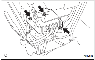
- Disconnect the 3 connectors from the center airbag sensor assembly.
- Remove the 3 bolts and the center airbag sensor assembly.
 On-vehicle inspection
1. INSPECT CENTER AIRBAG SENSOR ASSEMBLY
(VEHICLE NOT INVOLVED IN COLLISION)
Perform a diagnosis system check.
2. INSPECT CENTER AIRBAG SENSOR ASSEMBLY
(VEHICLE INVOLVED IN COLLISION AN ...
 Installation
1. INSTALL CENTER AIRBAG SENSOR ASSEMBLY
Check that the ignition switch is off.
Check that the battery negative (-) terminal is
disconnected.
CAUTION:
After disconnecting ...
Other materials:
Installation
1. INSTALL POWER POINT SOCKET ASSEMBLY
Engage the 2 claws to install the power point socket
assembly.
2. INSTALL QUARTER TRIM FRONT PANEL ASSEMBLY
LH
3. INSTALL BACK DOOR SCUFF PLATE
4. INSTALL BACK DOOR WEATHERSTRIP
5. INSTALL REAR DOOR WEATHERSTRIP LH
6. INSTALL REAR DOOR S ...
Disposal
HINT:
When scrapping a vehicle equipped with the SRS or
disposing of the steering pad, be sure to deploy the airbag
first in accordance with the procedure described below. If any
abnormality occurs with airbag deployment, contact the
SERVICE DEPT. of TOYOTA MOTOR SALES, U.S.A., INC.
CAUTION:
...
Short to GND in Rear Curtain Shield Squib LH
Circuit
DTC B1637/85 Short to GND in Rear Curtain Shield Squib LH
Circuit
DESCRIPTION
The rear curtain shield squib LH circuit consists of the center airbag sensor
assembly and the curtain
shield airbag assembly LH.
The circuit instructs the SRS to deploy when deployment conditions are met.
DTC ...
