Toyota Sienna Service Manual: System normal condition check
1. CHECK NORMAL CONDITION
- If the symptom is applicable to any of the following, it is intended behavior, and not a malfunction.
|
Symptom |
Answer |
| A longer route than expected is chosen. | Depending on the road conditions, the radio and navigation assembly may determine that a longer route is quicker. |
| Even when distance priority is high, the shortest route is not shown. | Some paths may not be advised due to safety concerns. |
| When the vehicle is put into motion immediately after the engine starts, the navigation system deviates from the actual position. | If the vehicle starts before the navigation system activates, the system may not react. |
| When running on certain types of roads, especially new roads, the vehicle position deviates from the actual position. | When the vehicle is driving on new roads not available on the map disc, the system attempts to match it to another nearby road, causing the position mark to deviate. |
- The following symptoms are not a malfunction, but are caused by errors inherent in the GPS, gyro sensor, speed sensor, and radio and navigation assembly.
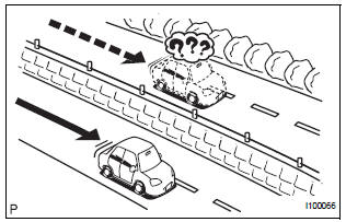
- The current position mark may be displayed on a nearby parallel road.
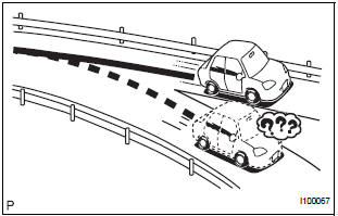
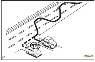
- Immediately after a fork in the road, the current vehicle position mark may be displayed on the wrong road.
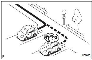
- When the vehicle turns right or left at an intersection, the current vehicle position mark may be displayed on a nearby parallel road.

- When the vehicle is carried, such as on a ferry, and the vehicle itself is not running, the current vehicle position mark may be displayed in the position where the vehicle was until a measurement can be performed by GPS.
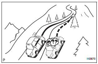
- When the vehicle runs on a steep hill, the current vehicle position mark may deviate from the correct position.

- When the vehicle makes a continuous turn of 360, 720, 1,080, etc. degrees, the current vehicle position mark may deviate from the correct position.
- When the vehicle moves erratically, such as constant lane changes, the current vehicle position mark may deviate from the correct position.
- When the ignition switch is turned to the ACC or ON position on a turntable before parking, the current vehicle position mark may not point in the correct direction. The same will occur when the vehicle comes out of parking.
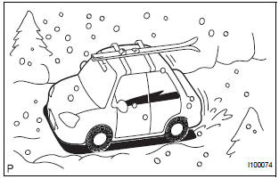
- When the vehicle runs on a snowy road or a mountain path with the chains installed or using a spare tire, the current vehicle position mark may deviate from the correct position.
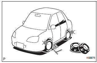
- When a tire is changed, the current vehicle position mark may deviate from the correct position.
HINT:
- Diameter of the tire may change, causing a speed sensor error.
- Performing the "tire change" in calibration mode will allow the system to correct the current vehicle position faster.
 Identification of noise source
1. Radio Description
Radio frequency band
Radio broadcasts use the radio frequency bands
shown in the table below
Service area
The service areas of AM and FM broa ...
 Display check mode
HINT:
This mode checks the color display on the display.
Illustrations may differ from the actual vehicle depending
on the device settings and options. Therefore, some
detailed a ...
Other materials:
Reverse Signal Circuit
DESCRIPTION
The radio and navigation assembly receives a reverse signal from the
park/neutral position switch.
WIRING DIAGRAM
INSPECTION PROCEDURE
1 INSPECT RADIO AND NAVIGATION ASSEMBLY
Disconnect the radio and navigation assembly connector
R12.
Measure the voltage accor ...
Power Slide Door Warning Buzzer RH does not Sound
DESCRIPTION
The power slide door system uses warning buzzers built into RH
slide doors respectively. Each buzzer
has 2 ways of sounding that are used differently according to the
situations:
When all the following conditions are met, the warning buzzer sounds at
a cycle of ...
Registering and connecting from the ÔÇťBluetooth* SetupÔÇŁ screen
To display the screen shown below, press the ÔÇťSETUPÔÇŁ button and
select ÔÇťBluetooth*ÔÇŁ on the ÔÇťSetupÔÇŁ screen.
Select to connect the device to
be used with audio system.
Select to register a Bluetooth® device to be used with audio system.
Select to set detailed
Blueto ...
