Toyota Sienna Service Manual: On-vehicle inspection
1. INSPECT FUEL CUT RPM
(a) Increase the engine speed to at least 3500 rpm.
(b) Use a sound scope to check for injector operating sounds.
(c) Check that when the throttle lever is released, injector operating sounds stop momentarily (at 2500 rpm) and then resume (at 1400 rpm).
Standard 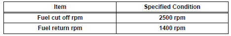
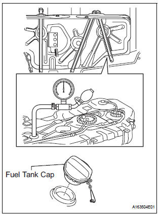
2. CHECK AIR TIGHTNESS IN FUEL TANK AND FILLER PIPE

(a) Disconnect the vent line hose from the fuel tank.
(b) Connect the pressure gauge to the fuel tank.
(c) Apply pressure to the fuel tank to create an internal pressure of 4 kPa (41 gf/cm2, 0.58 psi).
(d) Check that the internal pressure of the fuel tank is maintained for 1 minute.
(e) Check the connected portions of each hose and pipe.
(f) Check the installed parts on the fuel tank.
If any malfunctions, damage or other problems are found, replace the fuel tank and filler pipe.
(g) Reconnect the vent line hose to the fuel tank.
3. INSPECT FUEL CUT OFF VALVE AND FUEL CHECK VALVE
(a) Disconnect the vent line hose from the fuel tank.
(b) Connect the pressure gauge to the fuel tank.
(c) Fill the fuel tank with fuel.
(d) Apply pressure of 4 kPa (41 gf/cm2, 0.58 psi) to the vent port of the fuel tank.
HINT: Check the amount of fuel in the fuel tank. When the fuel tank is full, the float valve of the fill check valve is closed and no air can pass through.
(e) Remove the fuel tank cap, and check that the pressure drops.
If the pressure does not drop, replace the fuel tank assembly.
(f) Reconnect the vent line hose to the fuel tank.
4. CHECK AIR INLET LINE
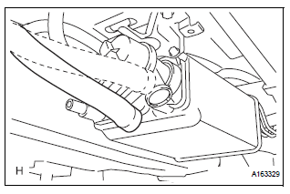
(a) Disconnect the air inlet line hose from the charcoal canister.
(b) Check that air can flow freely into the air inlet line.
If air cannot flow freely into the air inlet line, repair or replace it.
(c) Reconnect the air inlet line hose to the charcoal canister.
5. VISUALLY INSPECT HOSES, CONNECTORS AND GASKETS
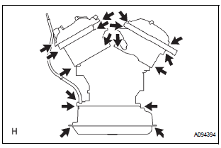
(a) Check for cracks, leaks or damage.
HINT:
Removal or problems with the engine oil dipstick, oil filler cap, PCV hose and other components may cause the engine to run improperly. Disconnection, looseness or cracks in the parts of the air induction system between the throttle body and cylinder head will allow air suction and cause the engine to run improperly.
If necessary, replace any damaged parts.
 Parts location
System diagram
...
 Canister
Components
...
Other materials:
Diagnosis system
1. CHECK DLC3
The vehicle's ECU uses ISO 15765-4 for
communication protocol. The terminal arrangement
of the DLC3 complies with SAE J1962 and matches
the ISO 15765-4 format.
NOTICE:
*: Before measuring the resistance, leave the
vehicle as is for at least 1 minute and do not
...
Diagnosis system
1. DESCRIPTION
Front power seat control system data can be read
through the Data Link Connector 3 (DLC3) of the
vehicle. When the system seems to be
malfunctioning, use the intelligent tester to check for
malfunctions and perform repairs.
2. CHECK DLC3
The vehicle us ...
Air conditioning controls
Adjusting the temperature setting
Turn the “TEMP” dial clockwise to increase the temperature and
counterclockwise to decrease the temperature.
The “SYNC” button
The air conditioning system switches between individual (indicator(
s) off) and simultaneous (indicators on) modes.
Whe ...
