
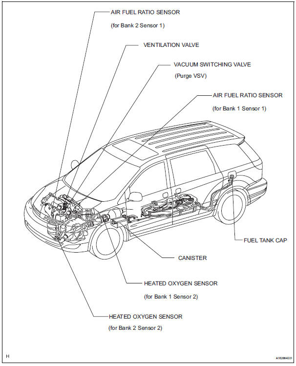
Toyota Sienna Service Manual: Parts location
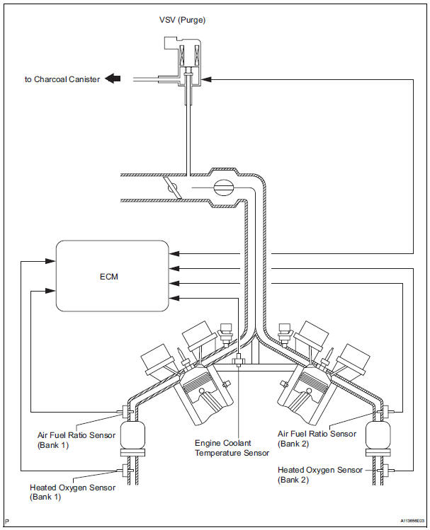
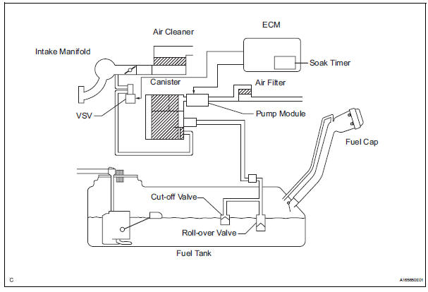
System diagram

 On-vehicle inspection
1. INSPECT FUEL CUT RPM
(a) Increase the engine speed to at least 3500 rpm.
(b) Use a sound scope to check for injector operating
sounds.
(c) Check that when the throttle lever is released,
i ...
Other materials:
TC and CG Terminal Circuit
DESCRIPTION
Connecting terminals TC and CG of the DLC3 causes the ECU to display the DTC
by blinking the ABS
warning light and/or VSC warning light.
WIRING DIAGRAM
INSPECTION PROCEDURE
NOTICE:
When replacing the brake actuator assembly, perform zero point calibration
(See page BC-70).
...
Diagnosis system
1. DESCRIPTION
Front power seat control system data can be read
through the Data Link Connector 3 (DLC3) of the
vehicle. When the system seems to be
malfunctioning, use the intelligent tester to check for
malfunctions and perform repairs.
2. CHECK DLC3
The vehicle us ...
All Doors cannot be Locked / Unlocked at Once
DESCRIPTION
The body ECU receives a switch signal from the master switch, the door
control switch, the driver door
key cylinder and the passenger door key cylinder and then drives the door lock
motor.
WIRING DIAGRAM
INSPECTION PROCEDURE
1 INSPECT FUSE (ECU-B)
Remove ECU-B fuse f ...
