Toyota Sienna Service Manual: On-vehicle inspection
HINT: The type of ignition switch on this model differs according to the specifications of the vehicle. For the expressions used in this section, refer to the "EXPRESSIONS OF IGNITION SWITCH" precaution (See page ES-1).
1. CHECK AIR FUEL RATIO COMPENSATION SYSTEM
(a) Connect the intelligent tester to the DLC3.
(b) Turn the ignition switch to the ON position.
(c) Select the following menu items: Data List / A/FS B1 S1 and O2S B1 S2.
(d) Warm up the A/F sensor with the engine speed at 2500 rpm for approximately 2 minutes.
(e) Keep the engine speed at 2500 rpm and confirm that the "A/FS B1 S1" and "A/FS BS S1" display is as shown in the illustration.
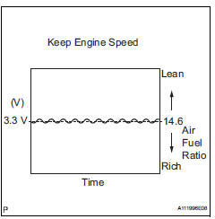
HINT:
- The illustration may slightly differ from the display on the intelligent tester.
- Only the intelligent tester displays the waveform of the A/F sensor.
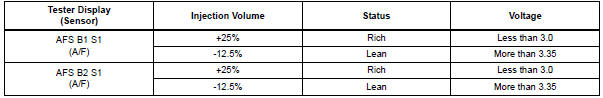
- On the tester, select the following menu items: DIAGNOSIS / ENHANCED OBD II / ACTIVE TEST / A/F CONTROL.
- The A/F CONTROL operation lowers the fuel injection volume by 12.5% or increases the injection volume by 25%.
- The sensors react in accordance with increases and decreases in the fuel injection volume.
Standard
| NOTICE: The A/F sensor has an output delay of a few seconds. |
(f) Confirm that the "O2S B1 S2" and "A/FS BS S1" display changes between 0 to 1 V with the engine speed at 2500 rpm.
OK: The voltage output oscillates more than 8 times in 10 seconds.
NOTICE:
|
 Air fuel ratio sensor (for 2wd)
Components
...
 Removal
1. DISCONNECT CABLE FROM NEGATIVE BATTERY
TERMINAL
2. REMOVE AIR FUEL RATIO SENSOR (for Bank 2
Sensor 1)
(a) Disconnect the sensor connector.
(b) Using SST, remove the sensor from the exhau ...
Other materials:
Washer fluid
If any washer does not work or the
warning message appears on the
multi-information display, the
washer tank may be empty. Add
washer fluid.
WARNINGWhen refilling washer fluid
Do not refill washer fluid when the engine is hot or running, as
washer fluid
contains alcohol and ...
CD Sound Skips
INSPECTION PROCEDURE
1 CHECK CD
Check the CD.
OK:
The CD is clean.
HINT:
If dirt is on the CD surface, wipe it clean with a soft cloth
from the inside to the outside in a radial direction.
NOTICE:
Do not use a conventional record cleaner or antistatic
preservative.
2 CHECK CD
...
Description of code registration
It is necessary to register the transmitter ID in the tire
pressure warning ECU when replacing the tire pressure
warning valve and transmitter and/or tire pressure
warning ECU.
(a) Before registration
(1) In case of tire pressure warning ECU
replacement.
Read the registered transmitter I ...
