Toyota Sienna Service Manual: On-vehicle inspection
HINT: The type of ignition switch on this model differs according to the specifications of the vehicle. For the expressions used in this section, refer to the "EXPRESSIONS OF IGNITION SWITCH" precaution (See page ES-1).
1. CHECK AIR FUEL RATIO COMPENSATION SYSTEM
(a) Connect the intelligent tester to the DLC3.
(b) Turn the ignition switch to the ON position.
(c) Select the following menu items: Data List / A/FS B1 S1 and O2S B1 S2.
(d) Warm up the A/F sensor with the engine speed at 2500 rpm for approximately 2 minutes.
(e) Keep the engine speed at 2500 rpm and confirm that the "A/FS B1 S1" and "A/FS BS S1" display is as shown in the illustration.
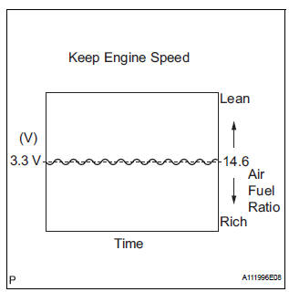
HINT:
- The illustration may slightly differ from the display on the intelligent tester.
- Only the intelligent tester displays the waveform of the A/F sensor.
- On the tester, select the following menu items: DIAGNOSIS / ENHANCED OBD II / ACTIVE TEST / A/F CONTROL
- The A/F CONTROL operation lowers the fuel injection volume by 12.5% or increases the injection volume by 25%
- The sensors react in accordance with increases and decreases in the fuel injection volume.
Standard 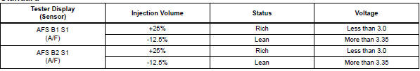
| NOTICE: The A/F sensor has an output delay of a few seconds. |
(f) Confirm that the "O2S B1 S2" and "A/FS BS S1" display changes between 0 to 1 V with the engine speed at 2500 rpm.
OK: The voltage output oscillates more than 8 times in 10 seconds.
NOTICE:
|
 Air fuel ratio sensor (for 4wd)
Components
...
 Removal
1. DISCONNECT CABLE FROM NEGATIVE BATTERY
TERMINALV
Caution:
wait at least 90 seconds after disconnecting the
cable from the negative (-) battery terminal to
prevent airbag and seat ...
Other materials:
Check for intermittent
problems
1. CHECK FOR INTERMITTENT PROBLEMS
HINT:
For use of the intelligent tester only:
Inspect the vehicle's ECM using check mode.
Intermittent problems are easier to detect with an
intelligent tester when the ECM is in check mode. In
check mode, the ECM uses 1 trip detection logic, which
is more ...
Throttle / Pedal Position Sensor / Switch "A/B"
Circuit
DTC P0120 Throttle / Pedal Position Sensor / Switch "A"
Circuit
DTC P0122 Throttle / Pedal Position Sensor / Switch "A"
Circuit Low Input
DTC P0123 Throttle / Pedal Position Sensor / Switch "A"
Circuit High Input
DTC P0220 Throttle / Pedal Position Sensor / Switch ...
Short in Front Passenger Side Squib Circuit
DTC B0105/53 Short in Front Passenger Side Squib Circuit
DESCRIPTION
The front passenger side squib circuit consists of the center airbag sensor
assembly and the front
passenger airbag assembly.
The circuit instructs the SRS to deploy when deployment conditions are met.
DTC B0105/53 is re ...
