Toyota Sienna Service Manual: Removal
1. DISCONNECT CABLE FROM NEGATIVE BATTERY TERMINALV
| Caution: wait at least 90 seconds after disconnecting the cable from the negative (-) battery terminal to prevent airbag and seat belt pretensioner activation. |
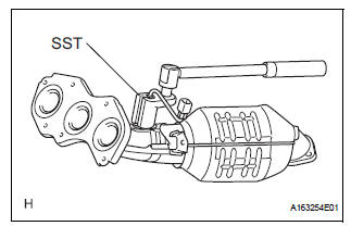
2. Remove air fuel ratio sensor (for bank 2 sensor 1)
(a) Disconnect the sensor connector.
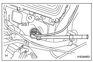
(b) Using SST, remove the sensor from the exhaust manifold.V
Sst 09224-00010
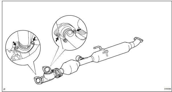
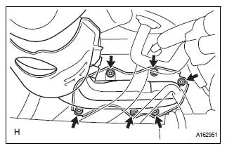
3. REMOVE CENTER EXHAUST PIPE ASSEMBLY
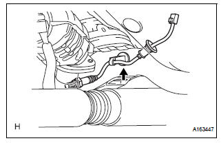
(a) Disconnect the heated oxygen sensor (for Bank 1 Sensor 2) connector under the center console.
(b) Remove the clip as shown in the illustration.
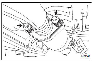
(c) Remove the 2 bolts and 2 compression springs.
(d) Remove the 2 bolts, 2 nuts and center exhaust pipe assembly.
4. REMOVE EXHAUST MANIFOLD RH
(a) Remove the nut, bolt and exhaust manifold stay.
(b) Remove the 6 nuts and exhaust manifold RH.
(c) Remove the gasket and exhaust manifold to head gasket.
5. REMOVE AIR FUEL RATIO SENSOR (for Bank 1 Sensor 1)
(a) Using SST, remove the sensor.
SST 09224-00010
 On-vehicle inspection
HINT:
The type of ignition switch on this model differs according to
the specifications of the vehicle. For the expressions used in
this section, refer to the "EXPRESSIONS OF IGNITION
SWITCH& ...
 Inspection
1. Inspect air fuel ratio sensor
(A) measure the resistance of the sensor.
Standard resistance
If the resistance is not as specified, replace the
sensor.
...
Other materials:
Installation
1. INSTALL SPIRAL CABLE
Check that the front wheels are facing straight
ahead.
Set the turn signal switch to the neutral position.
NOTICE:
If it is not in the neutral position, the pin of the
turn signal switch may snap.
Install the spiral cable.
NOTICE:
...
Removal
1. REMOVE FRONT WHEELS
2. REMOVE ENGINE UNDER COVER NO.1
3. DRAIN AUTOMATIC TRANSAXLE FLUID
(a) Remove the drain plug, gasket and drain ATF.
(b) Install a new gasket and the drain plug.
Torque: 49 N*m (500 kgf*cm, 36 ft.*lbf)
4. REMOVE FRONT DRIVE SHAFT ASSEMBLY LH
HINT:
(See page DS-6)
...
Illumination Circuit
DESCRIPTION
Power is supplied to the radio receiver and steering pad switch illumination
when the light control switch is
in the TAIL or HEAD position.
WIRING DIAGRAM
INSPECTION PROCEDURE
NOTICE:
The vehicle is equipped with an SRS (Supplemental Restraint System) which
includes
compon ...
