Toyota Sienna Service Manual: Only Back Door cannot be Opened
DESCRIPTION
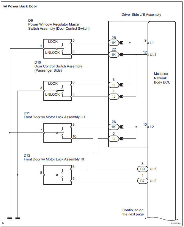
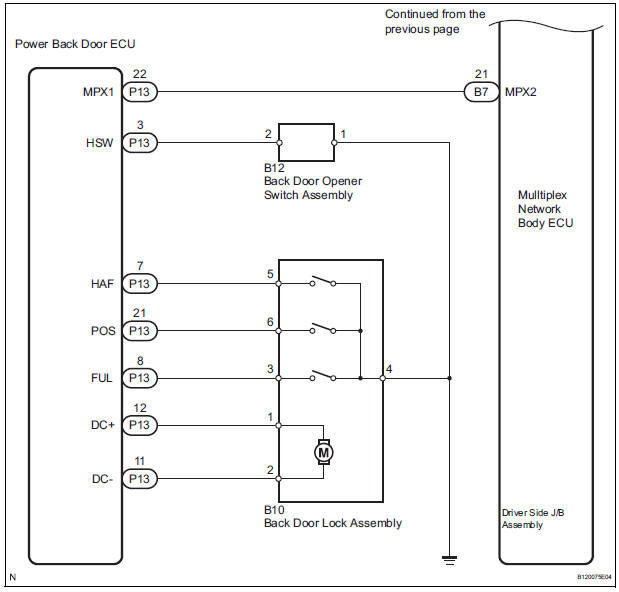
With power back door: The signal for manual locking/unlocking operation of the driver/passenger side door and the signal for locking/unlocking operation interlocked with the driver side door key cylinder are sent to the back door ECU from the body ECU using the MPX line. In response to these signals, the back door ECU causes the back door lock to be locked/unlocked. The ON signal of the back door opener switch, which is output when the switch is pressed, is directly sent to the back door ECU. In response to this signal, the back door ECU causes the back door lock to be open.
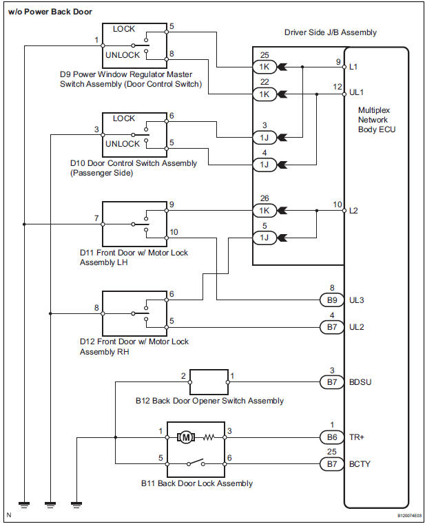
Without power back door: The signal for manual locking/unlocking operation of the driver/passenger side door and the signal for locking/unlocking operation interlocked with the driver side door key cylinder are sent to the body ECU. The ON signal of the back door opener switch, which is output when the switch is pressed, is sent to body ECU.
WIRING DIAGRAM
INSPECTION PROCEDURE
1 CHECK POWER BACK DOOR
- Choose the system to be inspected.

2 CHECK DTC
- Use the intelligent tester to check for normal function of the multiplex communication system.
- (ECU unconnected, communication line malfunctioning) Without DTC B1214, B1215 or B1287 outputs, proceed to A.
- (ECU unconnected, communication line malfunctioning) With DTC B1214, B1215 or B1287 outputs, proceed to B
3 PERFORM ACTIVE TEST BY INTELLIGENT TESTER
- Select the ACTIVE TEST and then check that the power door lock operates.
HINT: During the ACTIVE TEST, the intelligent tester sends a signal to the body ECU to drive all the power door lock motors. If all the power door locks operate, the power door lock motors and the harness between the power door lock motors and body ECU are considered to be functioning normally.
BODY (Multiplex network body ECU)

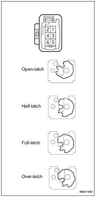
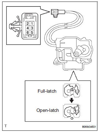
4 INSPECT BACK DOOR LOCK ASSEMBLY
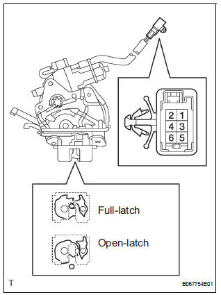
- Check operation of the door lock.
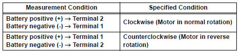
- Using a screwdriver, push the latch in order to put the back door lock in the locked condition (full-latch position).
- Connect the battery positive (+) lead to terminal 1
and the battery negative (-) lead to terminal 2.
Then, check operation of the latch.
Standard: The latch turns to the open-latch position
- Inspect motor operation when battery voltage is applied to the normals.
Standard
- Check the back door courtesy light switch resistance.
- Check the resistance between the terminals of the courtesy switch.
Standard resistance
- Check the back door latch switch resistance.
- Check the resistance between the terminals of the courtesy switch.
Standard resistance
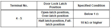
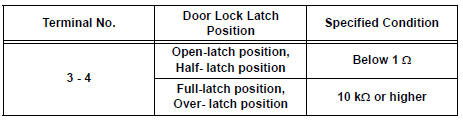
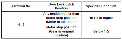
- Check the position switch resistance.
- Connect the battery positive (+) lead to connector terminal 1 and the negative (-) lead to connector terminal 2.
- Check the resistance between the terminals of the courtesy switch.
Standard resistance
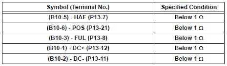
5 CHECK HARNESS AND CONNECTOR (BACK DOOR LOCK ASSEMBLY - POWER BACK DOOR ECU)
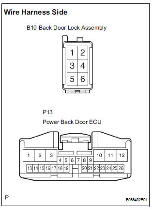
- Disconnect the B10 lock and P13 ECU connectors.
- Measure the resistance according to the value(s) in the table below.
Standard resistance
6 READ VALUE OF DATA LIST
- Using the intelligent tester, check the DATA LIST for proper functioning of the back door opener switch.
BODY (Multiplex network body ECU)

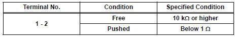
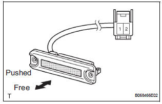
7 INSPECT BACK DOOR OPENER SWITCH ASSEMBLY
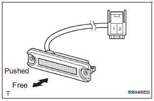
- Remove the back door opener switch.
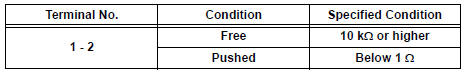
- Measure the resistance according to the value(s) in the table below.
Standard resistance
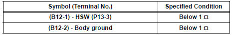
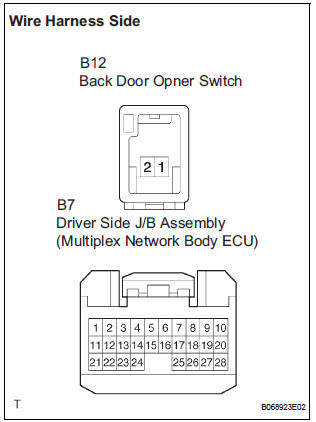
8 CHECK HARNESS AND CONNECTOR (BACK DOOR OPENER SWITCH - POWER BACK DOOR ECU - BODY GROUND)
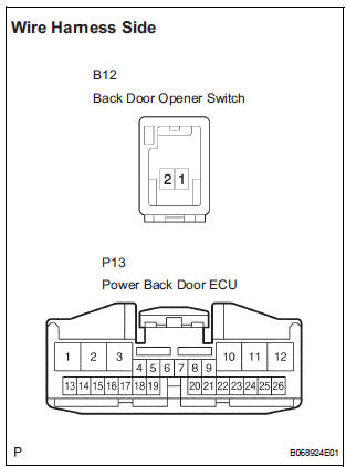
- Disconnect the B12 switch and P13 ECU connectors.
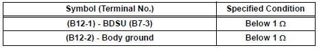
- Measure the resistance according to the value(s) in the table below.
Standard resistance
REPLACE DRIVER SIDE JUNCTION BLOCK ASSEMBLY (MULTIPLEX NETWORK BODY ECU)
9 PERFORM ACTIVE TEST BY INTELLIGENT TESTER
- Select the ACTIVE TEST and then check that the power door lock operates.
HINT: During the ACTIVE TEST, the intelligent tester sends a signal to the body ECU to drive all the power door lock motors. If all the power door locks operate, the power door lock motors and the harness between the power door lock motors and body ECU are considered to be functioning normally.
BODY (Multiplex network body ECU)

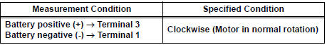
10 INSPECT BACK DOOR LOCK ASSEMBLY
- Check operation of the door lock.
- Using a screwdriver, push the latch in order to put the back door lock in the locked condition (full-latch position).
- Connect the battery positive (+) lead to terminal 3
and the battery negative (-) lead to terminal 1.
Then, check operation of the latch.
Standard: The latch turns to the open-latch position
- Inspect motor operation when battery voltage is applied to the normals.
Standard
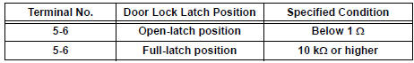
- Inspect the resistance of the courtesy switch
Standard resistance
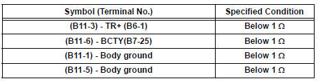
11 CHECK HARNESS AND CONNECTOR (BACK DOOR LOCK ASSEMBLY - DRIVER SIDE J/B)
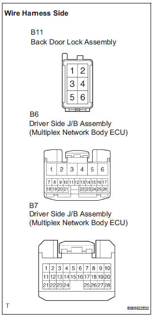
- Disconnect the B11 lock, B6 and P7 ECU connectors.
- Measure the resistance according to the value(s) in the table below.
Standard resistance
12 READ VALUE OF INTELLIGENT TESTER
- Using the intelligent tester, check the DATA LIST for proper functioning of the back door opener switch.
BODY

13 INSPECT BACK DOOR OPENER SWITCH ASSEMBLY
- Remove the back door opener switch.
- Measure the resistance according to the value(s) in the table below.
Standard resistance
14 CHECK HARNESS AND CONNECTOR (BACK DOOR OPENER SWITCH - DRIVER SIDE J/B)
- Disconnect the B12 switch and P7 ECU connectors.
- Measure the resistance according to the value(s) in the table below.
Standard resistance
REPLACE DRIVER SIDE JUNCTION BLOCK ASSEMBLY (MULTIPLEX NETWORK BODY ECU)
 Key Lock-in Prevention Function does not Work Properly (Manual
Operation and Operation Interlocked with Key are Active)
Key Lock-in Prevention Function does not Work Properly (Manual
Operation and Operation Interlocked with Key are Active)
DESCRIPTION
The un-lock warning switch turns ON when the key is inserted in the ignition
key cylinder. The courtesy
light switch turns ON when the driver side door is opened. These 2 switches are ...

Other materials:
Terminals of ECU
1. CHECK POWER SLIDE DOOR ECU LH
Disconnect the P25 and P26 ECU connectors, and
check the voltage and resistance of each terminal of
the wire harness side connectors
If the result is not as specified, there may be a
malfunction on the wire harness side.
Reconnect the EC ...
Installation
1. INSTALL REAR AXLE BEAM DAMPER
(a) Install the rear axle beam damper to the rear axle
beam assembly.
2. INSTALL REAR AXLE CARRIER BUSH LH
(a) Align the matchmarks on the axle beam assembly
with the 2 notches of a new bushing and temporarily
install the bushing to the rear axle beam assem ...
Engine assembly
Components
REMOVAL
1. DISCHARGE FUEL SYSTEM PRESSURE (See page
FU-13)
2. DISCHARGE REFRIGERANT FROM
REFRIGERATION SYSTEM (See page AC-172)
3. REMOVE BATTERY
(a) Disconnect the negative battery terminal.
(b) Disconnect the positive battery ...
