Toyota Sienna Service Manual: Open in Driver Side Squib 2nd Step Circuit
DTC B1181/18 Open in Driver Side Squib 2nd Step Circuit
DESCRIPTION
The driver side squib 2nd step circuit consists of the center airbag sensor assembly, the spiral cable and the steering pad.
The circuit instructs the SRS to deploy when deployment conditions are met.
DTC B1181/18 is recorded when an open circuit is detected in the driver side squib 2nd step circuit.
|
DTC No. |
DTC Detecting Condition |
Trouble Area |
|
B1181/18 |
|
|
INSPECTION PROCEDURE
HINT:
- Perform the simulation method by selecting the "check mode" (signal check) with the intelligent tester (8).
- After selecting the "check mode" (signal check), perform the simulation method by wiggling each connector of the airbag system or driving the vehicle on a city or rough road
1 CHECK STEERING PAD (DRIVER SIDE SQUIB 2ND STEP)
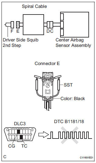
- Turn the ignition switch to the LOCK position.
- Disconnect the negative (-) terminal cable from the battery, and wait for at least 90 seconds.
- Disconnect the connectors from the steering pad.
- Connect the white wire side of SST (resistance 2.1 Ω) to the spiral cable.
CAUTION: Never connect a tester to the steering pad (driver side squib 2nd step) for measurement, as this may lead to a serious injury due to airbag deployment.
NOTICE: Do not forcibly insert the SST into the terminals of the connector when connecting.
Insert the SST straight into the terminals of the connector.
SST 09843-18060
- Connect the negative (-) terminal cable to the battery, and wait for at least 2 seconds.
- Turn the ignition switch to the ON position, and wait for at least 60 seconds.
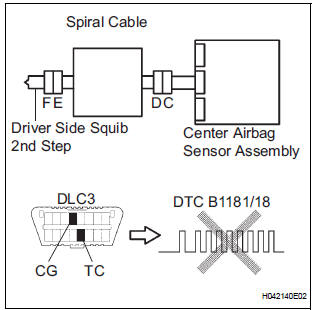
- Clear the DTCs stored in memory (5).
- Turn the ignition switch to the LOCK position.
- Turn the ignition switch to the ON position, and wait for at least 60 seconds.
- Check the DTCs (5).
OK: DTC B1181/18 is not output. HINT: Codes other than DTC B1181/18 may be output at this time, but they are not related to this check.
 Go to step 2

REPLACE STEERING PAD
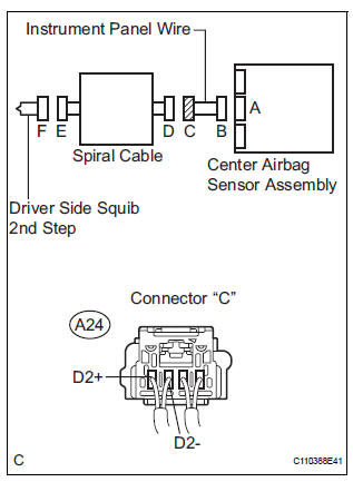
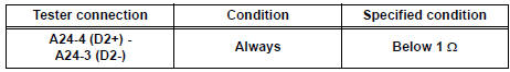
2 CHECK DRIVER SIDE SQUIB 2ND STEP CIRCUIT
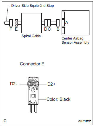
- Turn the ignition switch to the LOCK position.
- Disconnect the negative (-) terminal cable from the battery, and wait for at least 90 seconds.
- Disconnect the SST (resistance 2.1 Ω) from the spiral cable.
- Disconnect the connector from the center airbag sensor assembly.
- Measure the resistance according to the value(s) in the table below.
Standard resistance
 Go to step 4

3 CENTER AIRBAG SENSOR ASSEMBLY
- Connect the connectors to the steering pad and the center airbag sensor assembly.
- Connect the negative (-) terminal cable to the battery, and wait for at least 2 seconds.
- Turn the ignition switch to the ON position, and wait for at least 60 seconds.
- Clear the DTCs stored in memory (5).
- Turn the ignition switch to the LOCK position.
- Turn the ignition switch to the ON position, and wait for at least 60 seconds.
- Check the DTCs (5).
OK: DTC B1181/18 is not output.
HINT: Codes other than DTC B1181/18 may be output at this time, but they are not related to this check.
 REPLACE CENTER AIRBAG SENSOR
ASSEMBLY
REPLACE CENTER AIRBAG SENSOR
ASSEMBLY

USE SIMULATION METHOD TO CHECK
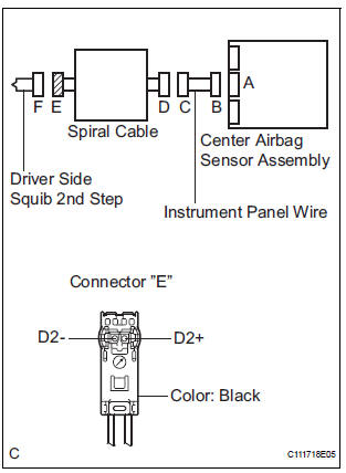
4 CHECK INSTRUMENT PANEL WIRE
- Disconnect the instrument panel wire connector from the spiral cable.
- Measure the resistance according to the value(s) in the table below.
Standard resistance
 REPAIR OR REPLACE INSTRUMENT
PANEL
WIRE
REPAIR OR REPLACE INSTRUMENT
PANEL
WIRE

5 CHECK SPIRAL CABLE
- Measure the resistance according to the value(s) in the table below.
Standard resistance
 REPLACE SPIRAL CABLE

USE SIMULATION METHOD TO CHECK
 Short in Driver Side Squib 2nd Step Circuit
DTC B1180/17 Short in Driver Side Squib 2nd Step Circuit
DESCRIPTION
The driver side squib 2nd step circuit consists of the center airbag sensor
assembly, the spiral cable and
the steering pad.
...
 Short to GND in Driver Side Squib 2nd Step Circuit
DTC B1182/19 Short to GND in Driver Side Squib 2nd Step Circuit
DESCRIPTION
The driver side squib 2nd step circuit consists of the center airbag sensor
assembly, the spiral cable and
the steering ...
Other materials:
How to proceed with
troubleshooting
1 VEHICLE BROUGHT INTO A WORKSHOP
2 DIAGNOSTIC QUESTIONING AND SYMPTOM CONFIRMATION
Ask the customer about symptoms and confirm
malfunctions.
3 CONFIRM THE SYSTEM NORMAL CONDITION
4 CHECK DTC
HINT:
If the system cannot enter the diagnosis mode, inspect each
AVC-LAN communication signal ...
Safety information
for children
Observe the following precautions when children are in the vehicle.
Use a child restraint system appropriate for the child, until the
child becomes large enough to properly wear the vehicle’s seat
belt.
It is recommended that children sit in the rear seats to avoid
accidental
contact ...
Wrong Disc/ Disc cannot be Read
DTC 44-41 Wrong Disc
DTC 44-42 Disc cannot be Read
DESCRIPTION
DTC No.
DTC Detecting Condition
Trouble Area
44-41
An unsuitable disc is inserted
DVD
Television display assembly
44-42
The disc cannot be read.
IN ...
