Toyota Sienna Service Manual: Operation check
1. DETECTION RANGE MEASUREMENT AND INDICATOR CHECK
- Turn the IG switch ON.
- Move the shift lever to the R position (when the back sonar and rear clearance sonar is checked).
- With front clearance sonar:
Move the shift lever to the N position (when the front
clearance sonar is checked).
NOTICE: Apply the parking brake securely so that the vehicle does not move.
- Turn the clearance sonar main switch ON.
- Move a φ 60 mm (2.36 in.) pole around the sensor to measure the detection range of the sensor.
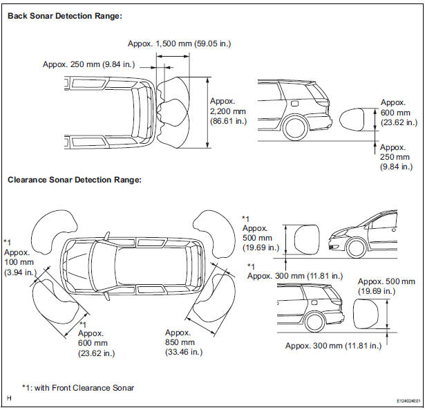
NOTICE: The measured detection range is for the φ60 mm (2.36 in.) pole. The detection range for walls and other obstacle is different.
- Check the indicator and the buzzer sounding condition when the back sonar sensor detects an obstacle.
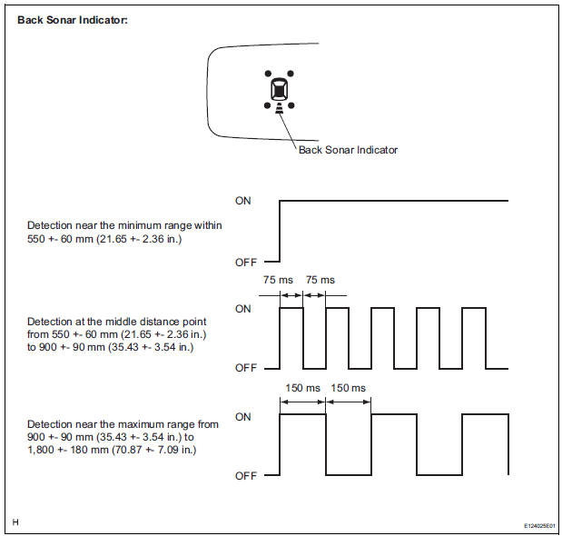
Operation condition

HINT: Since sound waves are used for the detection range measurement, the detection range may vary a little due to the outside air temperature.
- Check the indicator and the buzzer sounding condition when the rear clearance sonar sensor detects an obstacle
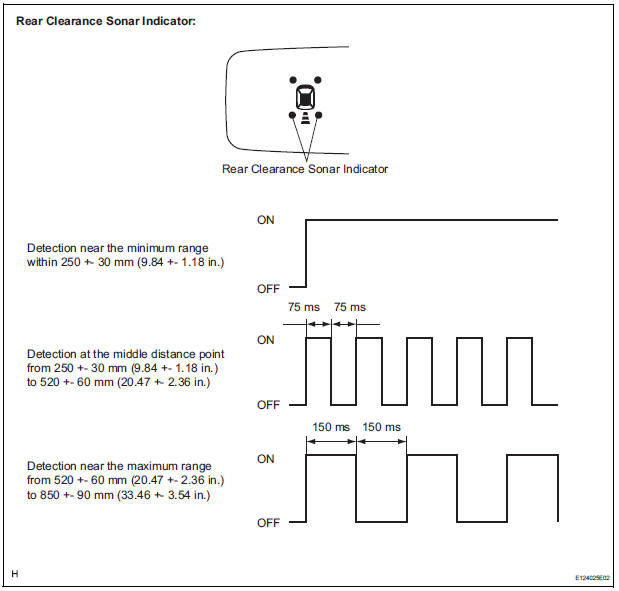
Operation condition

HINT: Since sound waves are used for the detection range measurement, the detection range may vary a little due to the outside air temperature
- With front clearance sonar: Check the indicator and the buzzer sounding condition when the front clearance sonar sensor detects an obstacle.
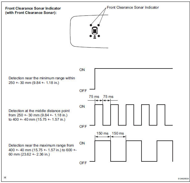
Operation condition

HINT: Since sound waves are used for the detection range measurement, the detection ranges may vary a little due to the outside air temperature.
2. CHECK INITIAL CHECK FUNCTION
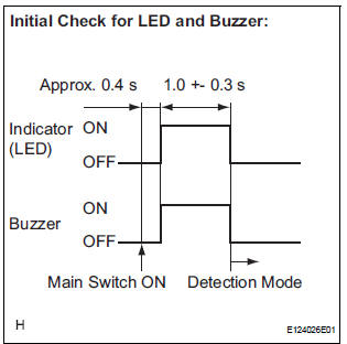
- Check the initial check function for the LED and
buzzer.
Turn the ignition switch and clearance main switch ON. The LED are buzzer will operate for about 1 second +- 0.3 seconds, regardless of shift lever position or vehicle speed. The system will then begin normal detection operation.
If the LED or buzzer is faulty, the relevant LED and buzzer operate as shown in the illustration below.
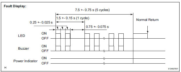
HINT:
- If each LED, power indicator and buzzer are not turned on continuously when power is turned on, the wire is broken.
- After the system returns to be normal, it conducts normal operation.
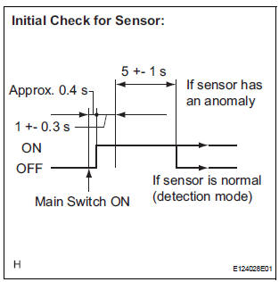
- Check the initial check function for the sensor.
For vehicles with 4 sensors:
- Approximately 0.4 seconds after the ignitin switch has been turned to the ON position, and the clearance sonar main switch has been turned on, all sensors will be checked by the system.
- The sensor check operation will continue for 5
seconds +/- 1 second. Even if one or more
sensors are anomalous, the sensor check
operation will be halted after 5 seconds +/- 1
second have elapsed.
For vehicles with 6 sensors:
- Approximately 0.4 seconds after the ignition switch has been turned to the ON position, and the clearance sonar main switch has been turned on, all sensors will be checked by the system.
- After 1 second +/- 0.3 seconds have elapsed, the check operation for all of the sensors will stop when a vehicle speed of over 10 km/h is detected.
- When the vehicle has been shifted from the P position, the system will change to obstacle detecting operation according to the shift position.
- If there are no changes in the conditions, such as those listed above (speed or shifter position), the sensor check operation will be halted after 5 seconds +/- 1 second have elapsed. If one or more sensors are anomalous, check operation for all of the sensors will continue (sensors will continue transmitting).
If the sensor is found to have an anomaly due to an open circuit or freezing for approximately 5 seconds or more, indications as shown in the following illustration appear.
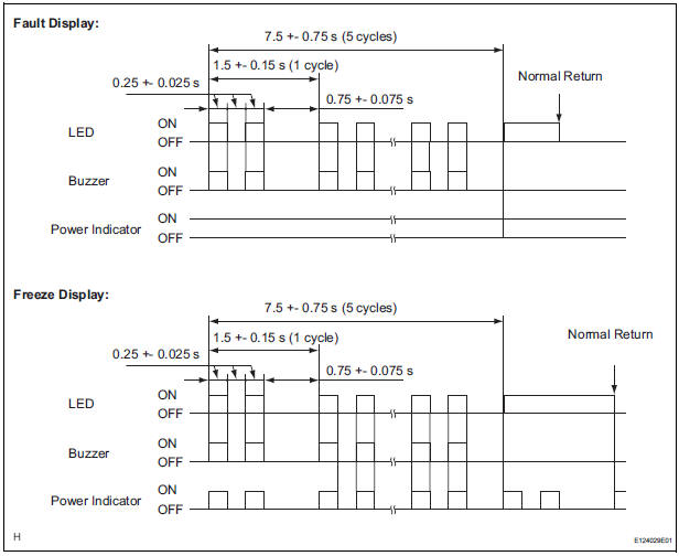
HINT:
- After the system returns to normal, it conducts normal operation.
- If one of the back sonar sensors is faulty, the other sensors will not be used to detect obstacles.
 How to proceed with
troubleshooting
How to proceed with
troubleshooting
1 VEHICLE BROUGHT TO WORKSHOP
2 CUSTOMER PROBLEM ANALYSIS
3 CHECK INITIAL CHECK FUNCTION
4 PROBLEM SYMPTOMS TABLE
THE CORRESPONDING SYSTEM DOES NOT EXIST (Go to step 5)
5 BASED ON THE MALFUNCTION ...
 Problem symptoms table
HINT:
Before performing verification listed in the table below,
check the fuse and relay.
Check the circuits for each problem symptom in the order
given in the table below, and p ...
Other materials:
On-vehicle inspection
1. INSPECT FRONT PASSENGER AIRBAG ASSEMBLY
(VEHICLE NOT INVOLVED IN COLLISION)
Perform a diagnostic system check.
With the front passenger airbag assembly installed
on the vehicle, perform a visual check. If there are
any defects as mentioned below, replace the
instrumen ...
Terminals of ECU
1. CHECK POWER SLIDE DOOR ECU LH (WITH
POWER SLIDE DOOR)
Disconnect the P25 and P26 ECU connectors, and
check the voltage and resistance of each terminal of
the wire harness side connectors.
If the result is not as specified, there may be a
malfunction on the wire harness side.
...
Diagnosis system
DESCRIPTION
(a) When troubleshooting OBD II (On-Board
Diagnostics) vehicles, an intelligent tester
(complying with SAE J1987) must be connected to
the DLC3 (Data Link Connector 3) of the vehicle.
Various data in the vehicle's ECM (Engine Control
Module) can be then read.
(b) OBD II regu ...
