Toyota Sienna Service Manual: On-vehicle inspection
1. INSPECT COOLING FAN SYSTEM
(a) Put the vehicle in the following conditions
(1) The engine switch is off.
(2) The coolant temperature is less than 95°C (203°F).
(3) The battery voltage is between 9 and 14 V.
(4) The A/C switch is OFF.
(b) Clamp the 400 A probe of an ammeter over the M+ wire of each cooling fan motor.
(c) Turn the ignition switch to the ON position and wait for approximately 10 seconds. Check that the fan stops.
(d) Start the engine. Check that the fan stops with the engine idling.
HINT:
- Make sure that the radiator engine coolant temperature is less than 95°C (203°F).
- Turn the A/C switch OFF.
(e) Check that the fan operates when the A/C switch is turned ON (MAX COOL and the magnetic clutch is operating).
Standard current
HINT:
The coolant temperature is less than 95°C (203°F).
(f) Check that the fan operates when the engine coolant temperature sensor connector is disconnected.
Standard current
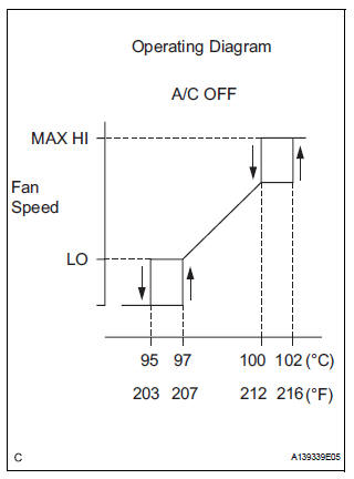
(g) After the engine is warmed up, check that the fan operates as shown in the illustration.
HINT:
- The coolant temperature at which the fan starts operating is approximately 95°C (203°F).
- This system can also be checked using the intelligent tester
- Select the following menu items: Powertrain / Engine / Data List / Initial Engine Coolant Temp.
 Precaution
NOTICE:
When the ignition switch is turned off and the engine
temperature is high, the cooling fans may operate for
approximately 3 minutes.
After turning the ignition switch of ...
 Coolant
Replacement
1. REMOVE NO. 1 ENGINE UNDER COVER (See page
EM-26)
2. REMOVE V-BANK COVER SUB-ASSEMBLY (See
page EM-28)
3. DRAIN ENGINE COOLANT
(a) Loosen the radiator drain cock plug.
HINT:
...
Other materials:
Diagnosis system
1. CHECK DLC3
The ECU uses ISO 15765-4 for communication.
The terminal arrangement of the DLC3 complies
with SAE J1962 and matches the ISO 15765-4
format.
NOTICE:
*: Before measuring the resistance, leave the
vehicle as is for at least 1 minute and do not
operate the ig ...
Camshaft Position Sensor
DTC P0365 Camshaft Position Sensor "B" Circuit (Bank 1)
DTC P0367 Camshaft Position Sensor "B" Circuit Low
Input (Bank 1)
DTC P0368 Camshaft Position Sensor "B" Circuit High
Input (Bank 1)
DTC P0390 Camshaft Position Sensor "B" Circuit (Bank 2)
DTC P0392 ...
Reassembly
1. INSTALL REAR SEAT STAY SUB-ASSEMBLY
Install the rear seat stay sub-assembly with the nut.
Torque: 5.5 N*m (56 kgf*cm, 49 in.*lbf)
2. INSTALL NO. 2 SEAT CUSHION SPRING ASSEMBLY
LH
3. INSTALL LOCUS CABLE LH
Install the locus cable LH with the nut.
Torque: 5.5 N*m (56 kg ...
