Toyota Sienna Service Manual: Parts location
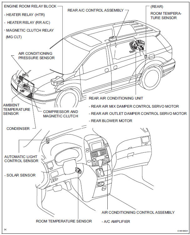
HOW TO PROCEED WITH TROUBLESHOOTING
1 VEHICLE BROUGHT TO WORKSHOP

2 CUSTOMER PROBLEM ANALYSIS
(a) Confirm problem symptoms.

3 CHECK AND CLEAR DTCS

4 PROBLEM SYMPTOM CONFIRMATION
5 SYMPTOM SIMULATION

6 DTC CHECK (OTHER THAN MULTIPLEX DTC)
7 DTC CHART

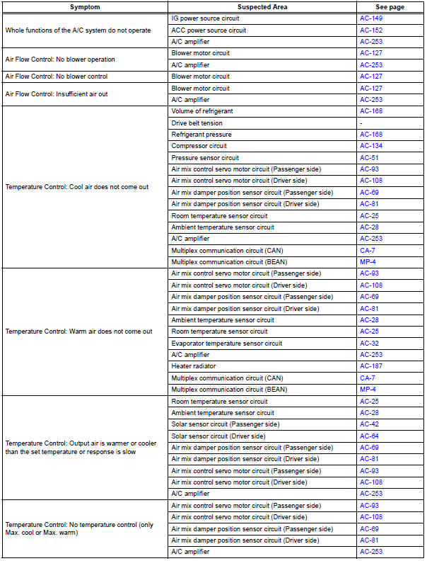
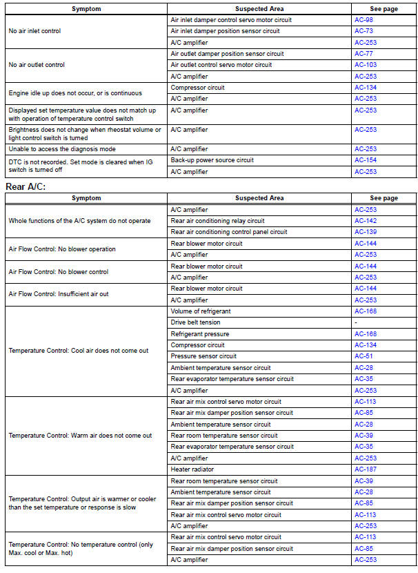
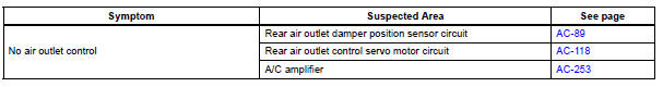
8 PROBLEM SYMPTOMS TABLE

9 TERMINALS OF ECU

10 CIRCUIT INSPECTION

11 IDENTIFICATION OF PROBLEM

12 REPAIR OR REPLACE

13 CONFIRMATION TEST

END
Problem symptoms table
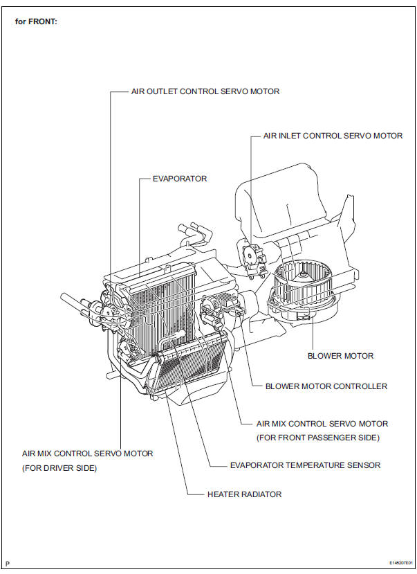
Front A/C:
 Precaution
NOTICE:
Because the compressor operates at high voltages, wear
electric insulated gloves and pull out the service plug to
cut the high-voltage circuit before inspection.
1. DO NOT HANDLE REFRIGERA ...
 Terminals of ecu
1. A/C AMPLIFIER
(a) Waveform 1:
(b) Waveform 2:
(c) Waveform 3: ...
Other materials:
Diagnostic trouble code chart
If a malfunction code is displayed during the DTC check,
check the circuit listed for that code in the table below.
(Proceed to the page given for that circuit.)
POWER BACK DOOR SYSTEM
DTC No.
Detection Item
Trouble Area
B2222
PBD Pulse Sensor Malfuncti ...
Abnormal Temperature Inside ID1 Tire
DESCRIPTION
Each tire pressure warning valve and transmitter measures the internal
temperature of its tire as well as
tire pressure, and transmits the information to the tire pressure warning ECU
along with the transmitter ID.
If the measured temperature is out of the specified range, t ...
Installation
1. Install heated oxygen sensor (for bank 2
sensor 2) (see page ec-34)
2. Install front exhaust pipe assembly
(a) Install 2 new gaskets to the front exhaust pipe
assembly.
(b) Install the front exhaust pipe assembly with the 4
nuts.
Torque: 62 n*m (632 kgf*cm, 46 ft.*Lbf)
3. INSTALL CE ...
