Toyota Sienna Service Manual: Memory Switch Circuit
DESCRIPTION
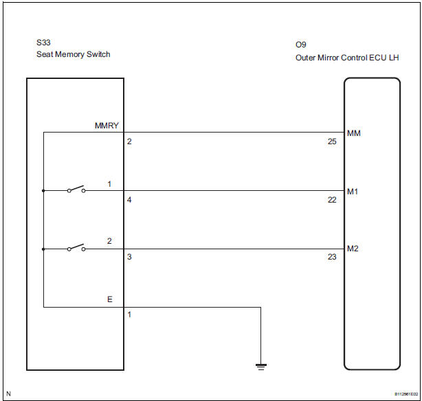
When the seat memory switch M1 or M2 is pressed, the position control ECU & switch (Seat ECU) transmits a signal of the memorized mirror position to the outer mirror control ECU. Then, the outer mirror control ECU drives the mirror motor.
HINT: The power mirror control system is a part of the multiplex communication system. This system features shared communication wiring that reduces the wiring complexity of the communication lines. The first step in any repair is to confirm the proper operation of the communication system. Proceed with troubleshooting after the communication has been verified (See the Multiplex Communication System).
WIRING DIAGRAM
INSPECTION PROCEDURE
1 READ VALUE OF INTELLIGENT TESTER
- Connect the intelligent tester to the DLC3.
- Ignition switch on.
- Enter the following menus: DIAGNOSIS / ENHANCED OBD II / DATA LIST.
- Check the DATA LIST for proper function of the seat memory switch.
D-SEAT
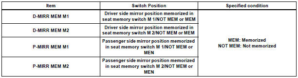
OK: Tester displayed MEM.
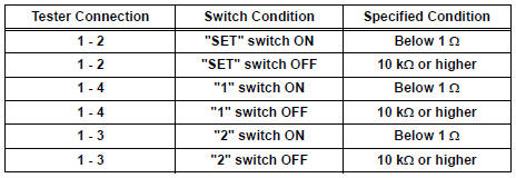
2 INSPECT SEAT MEMORY SWITCH
- Remove the seat memory switch.
- Measure the resistance according to the value(s) in the table below when the switch is operated.
Standard resistance
3 CHECK HARNESS AND CONNECTOR (SEAT MEMORY SWITCH - OUTER MIRROR CONTROL ECU)
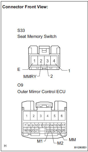
- Disconnect the S33 switch connector.
- Disconnect the O9 ECU connector.
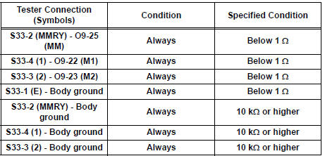
- Measure the resistance according to the value(s) in the table below.
Resistance
REPLACE OUTER MIRROR CONTROL ECU
 Position Sensor Circuit
DESCRIPTION
When SET and 1 or 2 are pressed, the position sensor detects the mirror
position and sends the signal to
the outer mirror control ECU. Then when position 1 or 2 is pressed, the outer
...
 Power Source Circuit
DESCRIPTION
This is the power source circuit for the outer mirror control ECU.
WIRING DIAGRAM
INSPECTION PROCEDURE
1 INSPECT OUTER MIRROR CONTROL ECU (POWER SOURCE)
Disconnect the O9 o ...
Other materials:
Past record
Type A
Press the “CAR” button.
Type B
Press the “APPS” button, and then select “Eco” on the screen.
If the “Trip Information” screen is displayed, select “Past Record”.
Reset the past record data
Best recorded fuel consumption
Average fuel consumption ...
DVD Player Mechanical Error/ DVD Insertion and Ejection Error/ DVD Reading
Abnormal
DTC 44-10 DVD Player Mechanical Error
DTC 44-11 DVD Insertion and Ejection Error
DTC 44-12 DVD Reading Abnormal
DESCRIPTION
TC No.
DTC Detection Condition
Trouble Area
44-10
A mechanical error in the DVD player is detected while
the DVD is not being insert ...
Panel Switches do not Function
INSPECTION PROCEDURE
1 CHECK PANEL SWITCH
Check for foreign matter around the switches that might
prevent operation.
OK:
No foreign matter is found
2 CHECK PANEL SWITCH (DISPLAY CHECK MODE)
Enter the "Display Check" mode (Panel Switch Check).
Operate the abnorma ...
