Toyota Sienna Service Manual: Installation
HINT: Install the RH side by the same procedure as the LH side.
1. INSTALL REAR SPEED SENSOR
(a) Clean the contacting surface of the axle hub and a new skid control sensor.
NOTICE: Keep the sensor rotor clean.
(b) Place the speed sensor on the axle hub so that the connector is positioned as shown in the illustration.
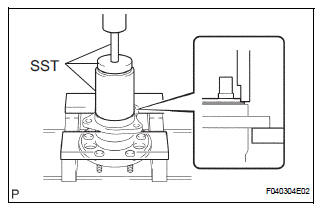
(c) Using SST and a press, install the skid control sensor to the axle hub.
SST 09214-76011
NOTICE:
- Do not tap the skid control sensor with a hammer directly.
- Check that there is no foreign matter on the skid control sensor detection portion.
- Press in the skid control sensor straight and slowly.
2. INSTALL REAR AXLE HUB & BEARING ASSEMBLY LH (See page AH-17)
3. INSTALL REAR BRAKE DRUM SUB-ASSEMBLY (for Drum Type)
(a) Aligning the matchmarks, install the rear brake drum sub-assembly.
4. INSTALL REAR DISC (for Disc Type)
(a) Aligning the matchmarks, install the rear disc.
5. INSTALL REAR DISC BRAKE CALIPER ASSEMBLY LH (for Disc Type)
(a) Install the rear disc brake caliper assembly LH with the 2 bolts.
6. SKID CONTROL SENSOR WIRE
(a) Connect the connector to the skid control sensor connector.
7. INSTALL REAR WHEEL
8. INSPECT AND ADJUST REAR WHEEL ALIGNMENT
HINT: See page SP-9.
9. CHECK ABS SPEED SENSOR SIGNAL
HINT: See page BC-10.
 Inspection
1. INSPECT REAR SPEED SENSOR
(a) Disconnect the skid control sensor connector.
(b) Measure the resistance between terminals 1 and 2
of the skid control sensor connector.
OK:
Resistance:
le ...
 Rear speed sensor (for 4wd)
Components
...
Other materials:
Removal
1. REMOVE BATTERY (See page EM-26)
2. REMOVE NO. 2 AIR CLEANER INLET (See page EM-
28)
3. REMOVE AIR CLEANER CAP SUB-ASSEMBLY (See
page FU-13)
4. REMOVE AIR CLEANER FILTER ELEMENT (See page
EM-28)
5. REMOVE AIR CLEANER CASE SUB-ASSEMBLY (See
page EM-28)
6. REMOVE AIR CLEANER BRACKET
(a ...
GCWR, TWR and Unbraked TWR
Confirm that the gross trailer weight, gross combination weight, gross
vehicle weight, gross axle weight and tongue weight are all within the
limits.
GCWR*
2WD models: 8900 lb. (4037 kg)
AWD models: 8990 lb. (4078 kg)
TWR*
3500 lb. (1588 kg)
Unbraked TWR*
1000 lb. (454 kg)
*: These models ...
Reassembly
1. INSTALL PLANETARY GEAR
(a) Apply grease to the planetary gears and pin parts of
the planetary shaft.
(b) Install the 3 planetary gears.
2. INSTALL STARTER ARMATURE ASSEMBLY
(a) Apply grease to the plate washer and the armature
shaft.
(b) Install the starter armature to the star ...
