Toyota Sienna Service Manual: Inspection procedure
1 BASIC INSPECTION
- Conditions necessary for the power slide door to open:
- Power slide door main switch is in the ON position (switch free: orange paint on the top of the switch appears).
- Slide door is unlocked (door lock position switch is in the ON position when the slide door is fully closed).
- Shift lever is in the P position when the ignition switch is ON (When the ignition switch is OFF, the power slide door operates at any position of the shift lever.)
- Conditions necessary for the power slide door to close:
- Power slide door main switch is in the ON position (switch free: orange paint on the top of the switch appears).
- Slide door is between approximately the half-open position and the fully open position.
- Slide door touch sensor is not damaged and deformed.
2 INSPECT FUSE (ECU-B)
- Inspect the ECU-B fuse
3 CHECK DTC
- Check for DTC B2223. DTC B2223 indicates a pulse sensor malfunction.
- Without code outputs, proceed to A.
- With code outputs, proceed to B.
4 INSPECT COMMUNICATION FUNCTION OF LARGE-SCALE MULTIPLEX COMMUNICATION SYSTEM (BEAN)
- Use the intelligent tester to check for normal function of the multiplex communication system.
- (ECU unconnected, communication line malfunctioning) Without DTC B1214, B1215 or B1216 outputs, proceed to A.
- (ECU unconnected, communication line malfunctioning) With DTC B1214, B1215 or B1216 outputs, proceed to B.
5 READ VALUE OF INTELLIGENT TESTER
- Using the intelligent tester, check the DATA LIST for proper functioning of the power slide door main switch.
OK (Power slide door ECU RH):
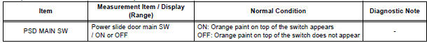
6 INSPECT POWER SLIDE DOOR MAIN SWITCH
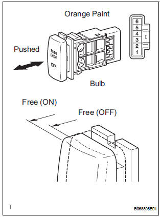
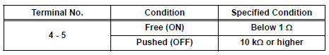
- Inspect the resistance of the main switch.
Resistance
HINT: If the switch does not illuminate, it will not affect the ON / OFF function of the switch. For the illumination check, refer to SLIDE DOOR SYSTEM
7 CHECK WIRE HARNESS (POWER SLIDE DOOR MAIN SWITCH - POWER SLIDE DOOR ECU RH)
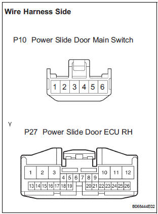
- Disconnect the P10 switch and P27 ECU connectors.
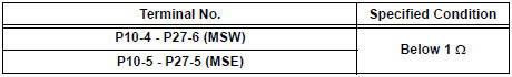
- Check the resistance between the wire harness side connectors.
Resistance (Check for open circuit)
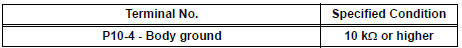
- Check the resistance between the P10 switch connector and body ground.
Resistance (Check for short circuit)
REPLACE POWER SLIDE DOOR ECU RH
8 CHECK SWITCH OPERATION
- If the power slide door does not respond to using the satellite switch, proceed to A.
- If the power slide door does not respond to using the power slide door control switch (child lock is set at UNLOCK.), proceed to B.
HINT: If the power slide door cannot operate using the power slide door control switch even when the child lock is locked, there may be a malfunction in the child lock switch. In this case, check the handle switch circuit
9 INSPECT SATELLITE SWITCH
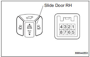
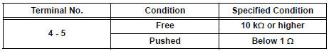
- Check the resistance of the RH switch.
Resistance
HINT: If the switch does not illuminate, it will not affect the ON / OFF function of the switch. For the illumination check, refer to SLIDE DOOR SYSTEM
10 CHECK WIRE HARNESS (SATELLITE SWITCH - DRIVER SIDE J/B, BODY GROUND)
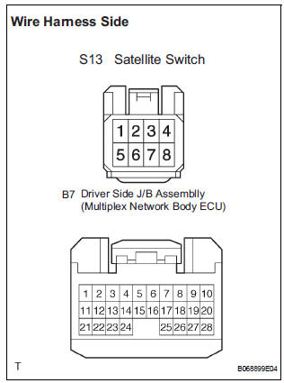
- Disconnect the S13 switch and B7 ECU connectors.
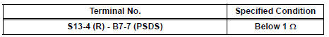
- Check the resistance between the wire harness side connectors.
Resistance (Check for open circuit)
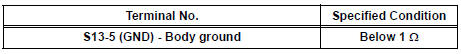
- Check the resistance between the S13 switch connector and body ground.
Resistance (Check for open circuit)
REPAIR OR REPLACE HARNESS AND CONNECTOR
11 READ VALUE OF INTELLIGENT TESTER
- Using the intelligent tester, check the DATA LIST for proper functioning of the power slide door control switch RH.
OK (Power slide door ECU RH):
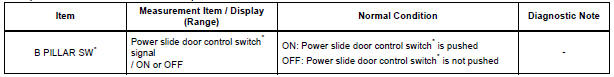
* "B PILLAR SW" appears on the display of the intelligent tester, however the name of the part corresponding to the display of the tester is "Power slide door control switch".
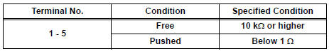
12 INSPECT POWER SLIDE DOOR CONTROL SWITCH RH
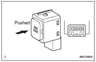
- Inspect the resistance of the switch.
Resistance
HINT: If the switch does not illuminate, it will not affect the ON / OFF function of the switch. For the illumination check, refer to SLIDE DOOR SYSTEM
13 CHECK WIRE HARNESS (POWER SLIDE DOOR CONTROL SWITCH RH - POWER SLIDE DOOR ECU RH)
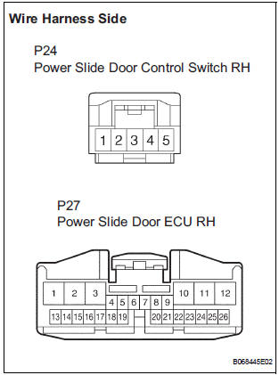
- Disconnect the P24 switch and P27 ECU connectors.
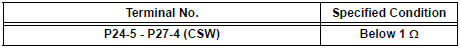
- Check the resistance between the wire harness side connectors.
Resistance (Check for open circuit)
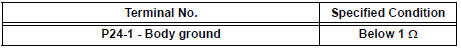
- Check the resistance between the P24 switch connector and body ground.
Resistance (Check for open circuit)
REPLACE POWER SLIDE DOOR ECU RH
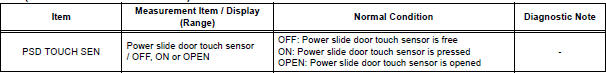
14 READ VALUE OF INTELLIGENT TESTER
- Using the intelligent tester, check the DATA LIST for proper functioning of the power slide door touch sensor RH.
OK (Power slide door ECU RH):
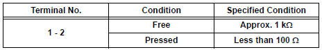
15 INSPECT POWER SLIDE DOOR TOUCH SENSOR RH
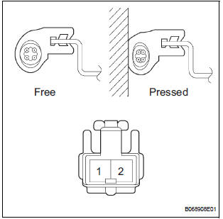
- Check the resistance of the sensor.
Resistance
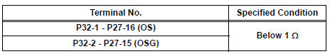
16 CHECK WIRE HARNESS (POWER SLIDE DOOR TOUCH SENSOR RH - POWER SLIDE DOOR ECU RH)
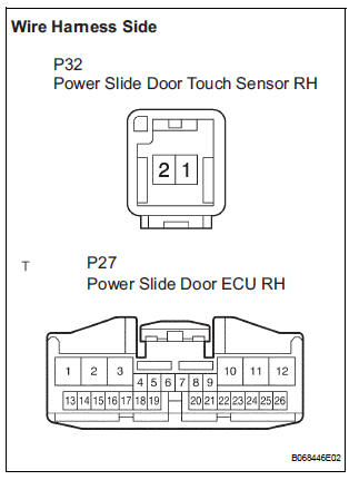
- Disconnect the P32 sensor and P27 ECU connectors.
- Check the resistance between the wire harness side connectors.
Resistance (Check for open circuit)
REPLACE POWER SLIDE DOOR ECU RH
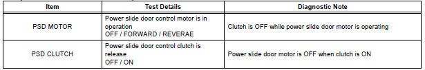
17 PERFORM ACTIVE TEST BY INTELLIGENT TESTER
- Select the ACTIVE TEST and then check that the power slide door control motor and clutch RH operates.
HINT: During the ACTIVE TEST, the intelligent tester sends a signal to the power slide door ECU RH to drive the motor and clutch. If the motor and clutch operates, the motor and clutch itself and the wire harness between the motor and clutch and the power slide door ECU RH are considered to be functioning normally.
OK (Power slide door ECU RH):
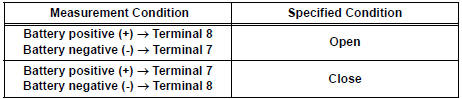
18 INSPECT SLIDE DOOR CONTROL MOTOR AND CLUTCH ASSEMBLY RH
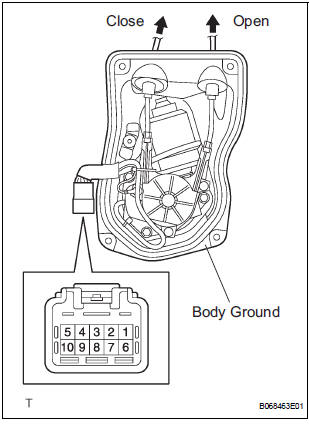
- Remove the motor and clutch.
- Connect the battery positive (+) lead to terminal 3 and battery negative (-) terminal lead to terminal 2.
- Apply battery voltage to the terminals and check the motor operation.
OK
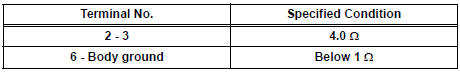
- Check the resistance of the clutch terminals.
Resistance
- Reinstall the motor and clutch with the connector connected.
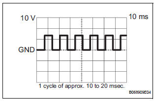
- Check the pulse of the pulse sensor.
- Using an oscilloscope, check the pulse generated when the door is manually opened and closed.
Reference
HINT: A cycle of the pulse changes between approx. 10 to 20 msec. according to the speeds that the slide door is moving.
NOTICE: When disconnecting the control motor and clutch, initialize the power slide door system
19 CHECK WIRE HARNESS (POWER SLIDE DOOR CONTROL MOTOR - POWER SLIDE DOOR ECU RH)
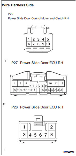
- Disconnect the P22 motor and clutch, the P27 and P28 ECU connectors.
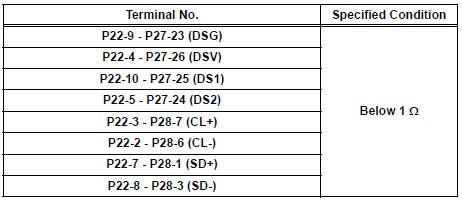
- Check the resistance between the wire harness side connectors.
Resistance (Check for open circuit)
REPLACE POWER SLIDE DOOR ECU RH
20 READ VALUE OF INTELLIGENT TESTER
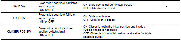
- Using the intelligent tester, check the DATA LIST for proper functioning of the switches listed below.
OK (Power slide door ECU RH):
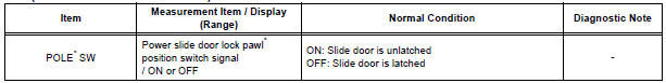
* "POLE" appears on the display of the intelligent tester, however the name of the part corresponding to the display of the tester is "pawl".
21 INSPECT POWER SLIDE DOOR LOCK ASSEMBLY RH
22 CHECK WIRE HARNESS (POWER SLIDE DOOR LOCK ASSEMBLY RH - POWER SLIDE DOOR ECU RH)
REPLACE POWER SLIDE DOOR ECU RH
23 PERFORM ACTIVE TEST BY INTELLIGENT TESTER
- Select the ACTIVE TEST and then check that the slide door lock release motor RH operates.
HINT: During the ACTIVE TEST, the intelligent tester sends a signal to the power slide door ECU RH to drive the release motor. If the release motor operates, the release motor itself and the wire harness between the release motor and power slide ECU RH are considered to be functioning normally.
OK (Power slide door ECU RH):

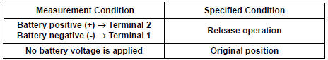
24 INSPECT SLIDE DOOR LOCK RELEASE MOTOR ASSEMBLY
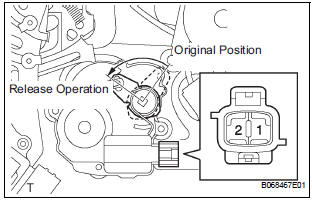
- Apply battery voltage and inspect operation of the release motor.
OK
25 CHECK WIRE HARNESS (SLIDE DOOR LOCK RELEASE MOTOR - POWER SLIDE DOOR ECU RH)
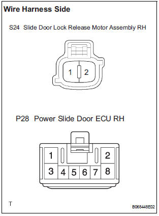
- Disconnect the S24 motor and P28 ECU connectors.
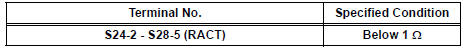
- Check the resistance between the wire harness side connectors.
Resistance (Check for open circuit)
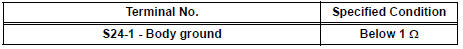
- Check the resistance between the S22 motor connector and body ground.
Resistance (Check for open circuit)
26 REPLACE POWER SLIDE DOOR ECU RH
- Check the power slide door for normal OPEN / CLOSE operation.
SYSTEM NORMAL
- Power Slide Door LH does not Operate When Using Inside / Outside Handle
- Power Slide Door RH does not Operate When Using Inside / Outside Handle
- Jam Protection Function Activates During Power Slide Door LH Operation
- Jam Protection Function Activates During Power Slide Door RH Operation
- Power Slide Door does not Fully Open
- Power Slide Door Warning Buzzer LH does not Sound
- Power Slide Door Warning Buzzer RH does not Sound
 Power Slide Door RH does not Operate When Satellite Switch is
Pressed
Power Slide Door RH does not Operate When Satellite Switch is
Pressed
DESCRIPTION
The power slide door operates only when the power slide door main
switch is ON (switch free: orange
paint on the top of the switch appears). The power slide door ECU RH
c ...
 Power Slide Door LH does not Operate When Using Inside / Outside
Handle
Power Slide Door LH does not Operate When Using Inside / Outside
Handle
DESCRIPTION
The inside / outside handles have the ability to control operation
of the power slide door. Pulling either
handle transmits a request signal to the power slide door ECU LH, ...
Other materials:
Short to B+ in Rear Curtain Shield Squib LH
Circuit
DTC B1638/86 Short to B+ in Rear Curtain Shield Squib LH
Circuit
DESCRIPTION
The rear curtain shield squib LH circuit consists of the center airbag sensor
assembly and the curtain
shield airbag assembly LH.
The circuit instructs the SRS to deploy when deployment conditions are met.
DTC B ...
Air conditioning controls
Adjusting the temperature setting
Press ÔÇťÔÇŁ on the ÔÇťTEMPÔÇŁ button to
increase the temperature and ÔÇťÔÇŁ
to decrease the temperature.
Adjusting the fan speed
Press ÔÇťÔÇŁ on
to increase the fan speed and ÔÇťÔÇŁ
to decrease
the fan speed.
Press the ÔÇťOFFÔÇŁ button to turn the ...
Data list / active test
1. DATA LIST
HINT:
Using the intelligent tester's DATA LIST allows the status
of a switch, sensor, actuator and other items to be read
without removing any parts. Reading the DATA LIST
early in troubleshooting is one way to save time.
Connect the intelligent tester (with CAN VIM) to t ...
