Toyota Sienna Service Manual: Power Slide Door Warning Buzzer RH does not Sound
DESCRIPTION
- The power slide door system uses warning buzzers built into RH slide doors respectively. Each buzzer has 2 ways of sounding that are used differently according to the situations:
- When all the following conditions are met, the warning buzzer sounds at a cycle of 0.3 seconds:
* The ignition switch is turned ON.
* The shift lever is moved into any position except P position.
* The slide door is open or the power slide door is activated to open.
The warning buzzer continues to sound until the slide door is fully closed or the shift lever is moved into the P position.
- While the power slide door is operating, the warning buzzer that notifies that the door is moving sounds at a cycle of 0.7 seconds. This stops sounding when the power slide door stops. This way of sounding is set to OFF at factory (default setting) and can be customized when required.
- The power slide door ECU RH directly sends a signal to the warning buzzer.
HINT:
- Only item 2 can be customized.
- If both items occur at the same time, item 1 is prior to the other.
WIRING DIAGRAM
INSPECTION PROCEDURE
1 PERFORM ACTIVE TEST BY INTELLIGENT TESTER
- Select the ACTIVE TEST and then check that the power slide door warning buzzer RH operates.
HINT: During the ACTIVE TEST, the intelligent tester sends a signal to the power slide door ECU RH to activate the warning buzzer. If the warning buzzer is activated, the warning buzzer itself and the wire harness between the warning buzzer and power slide door ECU RH are considered to be functioning normally.
OK (Power slide door ECU RH):

2 CHECK WIRE HARNESS (POWER SLIDE DOOR WARNING BUZZER RH - BODY GROUND)
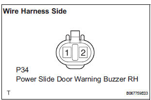
- Remove the buzzer connector.
- Inspect the buzzer connector side voltage.
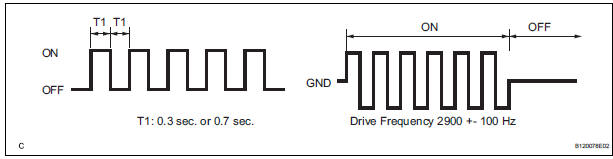
NOTICE: Use an oscilloscope to check the output voltages of the buzzer
Voltage

3 INSPECT POWER SLIDE DOOR WARNING BUZZER RH
- Check the resistance of the buzzer.
Resistance
NOTICE:
- The circuit that causes the buzzer to sounds is built into the slide door ECU, not around the buzzer.
- Directly applying battery voltage to the buzzer does not cause the buzzer to sound.
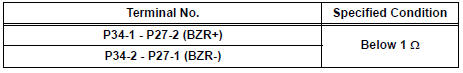
4 CHECK WIRE HARNESS (POWER SLIDE DOOR WARNING BUZZER RH - POWER SLIDE DOOR ECU RH)
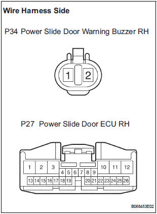
- Disconnect the P34 buzzer and the P27 ECU connectors.
- Check the resistance between the wire harness side connectors.
Resistance (Check for open circuit)
REPLACE POWER SLIDE DOOR ECU RH
 Power Slide Door Warning Buzzer LH does not Sound
DESCRIPTION
The power slide door system uses warning buzzers built into LH
slide doors respectively. Each buzzer
has 2 ways of sounding that are used differently according to the
sit ...
 Slide door closer system
PARTS LOCATION
...
Other materials:
Cruise control main switch
COMPONENTS
Removal
1. DISCONNECT BATTERY NEGATIVE TERMINAL
2. REMOVE STEERING WHEEL COVER LOWER NO.2
(24)
3. REMOVE STEERING WHEEL COVER LOWER NO.3
(24)
4. REMOVE HORN BUTTON ASSEMBLY
5. REMOVE CRUISE CONTROL MAIN SWITCH
Disconnect the connectors.
Remove the 2 ...
Illumination Circuit
DESCRIPTION
Power is supplied to the radio and navigation assembly and steering pad
switch illumination when the
light control switch is in the TAIL or HEAD position.
WIRING DIAGRAM
INSPECTION PROCEDURE
NOTICE:
The vehicle is equipped with an SRS (Supplemental Restraint System) such as t ...
Engine Coolant Temperature Circuit Range /
Performance Problem
DTC P0116 Engine Coolant Temperature Circuit Range /
Performance Problem
DESCRIPTION
Refer to DTC P0115
DTC No.
DTC Detection Condition
Trouble Area
P0116
ECTs as listed below are nearly same (2 trip detection
logic):
ECT when engine is start ...
