Toyota Sienna Service Manual: Power window regulator motor
INSPECTION
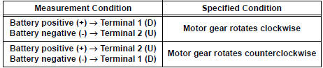
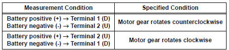
1. INSPECT POWER WINDOW REGULATOR MOTOR (FRONT RH)
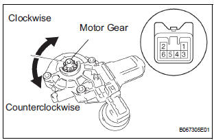
- Remove the power window regulator motor.
- Apply battery voltage to the motor connector according to the table below.
NOTICE: Do not apply battery to any terminals except terminals 1 and 2.
Standard
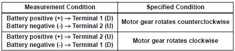
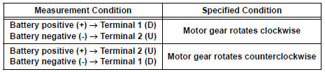
2. INSPECT POWER WINDOW REGULATOR MOTOR (FRONT LH)
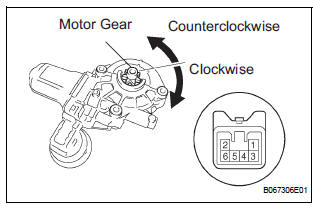
- Remove the power window regulator motor.
- Apply battery voltage to the motor connector according to the table below.
NOTICE: Do not apply battery to any terminals except terminals 1 and 2.
Standard
3. INSPECT POWER WINDOW REGULATOR NOTOR (REAR RH)

- Remove the power window regulator motor.
- Apply battery voltage to the motor connector according to the table below.
NOTICE: Do not apply battery to any terminals except terminals 1 and 2.
Standard
4. INSPECT POWER WINDOW REGULATOR MOTOR (REAR LH)

- Remove the power window regulator motor.
- Apply battery voltage to the motor connector according to the table below.
NOTICE: Do not apply battery to any terminals except terminals 1 and 2.
Standard
 Rear power window switch
INSPECTION
1. INSPECT POWER WINDOW REGULATOR SWITCH ASSEMBLY REAR
Check the resistance between the switch terminals
when the switch is operated.
Standard
If the result is not as ...
 Windshield glass
COMPONENTS
...
Other materials:
Diagnosis system
1. CHECK DLC3
The vehicle's ECU uses ISO 15765-4 for
communication protocol. The terminal arrangement
of the DLC3 complies with SAE J1962 and matches
the ISO 15765-4 format.
NOTICE:
*: Before measuring the resistance, leave the
vehicle as is for at least 1 minute and do ...
Removal
1. DISCONNECT CABLE FROM NEGATIVE BATTERY
TERMINAL
2. REMOVE HEATED OXYGEN SENSOR (for Bank 1
Sensor 2) (See page EC-38)
3. REMOVE TAIL EXHAUST PIPE ASSEMBLY
(a) Remove the 2 bolts.
(b) Disconnect the 4 exhaust pipe supports and remove
the tail exhaust pipe assembly.
(c) Remove the gas ...
Diagnosis system
1. DESCRIPTION
When troubleshooting a vehicle with the diagnosis
system, the only difference from the usual
troubleshooting procedure is connecting the intelligent
tester to the vehicle and reading various data output from
the vehicle's clearance warning ECU.
The clearance warning ECU record ...
