Toyota Sienna Service Manual: Precaution
NOTICE:
|
HINT: If all of the following are met for a certain period of time during a few minute period immediately before the engine is stopped, the electric fans will continue to operate for 3 minutes after the engine is stopped. This is performed to ensure restartability and stabilize idle speed.
– The intelligent tester indicates a very high coolant temperature.
– The intelligent tester indicates a high outside air temperature.
– The vehicle has been driven under high load (driving on an uphill or equivalent).
The following sensors are used for this control:
– Coolant temperature sensor
– Outside air temperature sensor
– MAF sensor
– Vehicle speed sensors
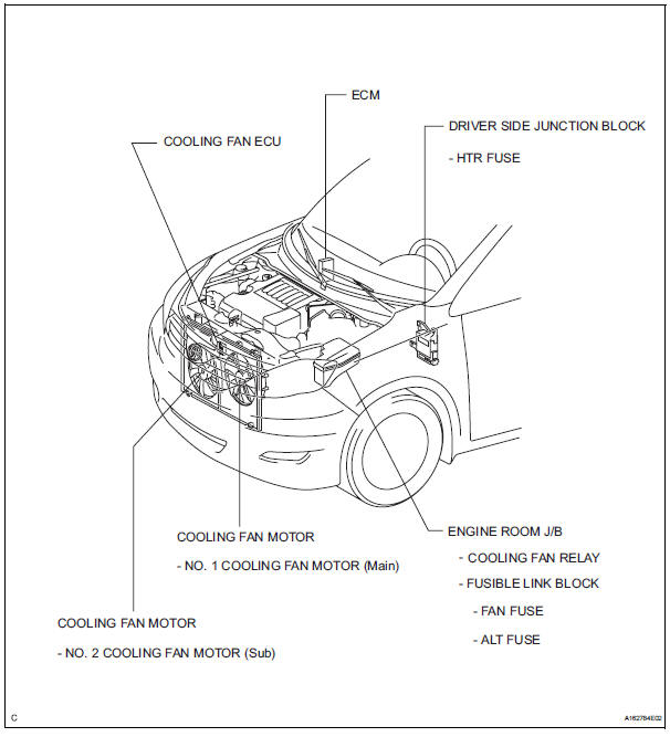
PARTS LOCATION
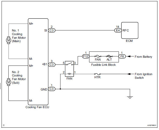
SYSTEM DIAGRAM

 On-vehicle inspection
1. INSPECT COOLING FAN SYSTEM
(a) Put the vehicle in the following conditions
(1) The engine switch is off.
(2) The coolant temperature is less than 95°C
(203°F).
(3) The battery voltage is ...
Other materials:
Diagnosis system
1. DESCRIPTION
When troubleshooting OBD II (On-Board
Diagnostics) vehicles, an intelligent tester
(complying with SAE J1987) must be connected to
the DLC3 (Data Link Connector 3) of the vehicle.
Various data in the vehicle's ECM (Engine Control
Module) can be then read.
& ...
Television display
COMPONENTS
Removal
1. REMOVE TELEVISION BASE
Release the 4 clips and remove the television base.
2. REMOVE TELEVISION DISPLAY ASSEMBLY
Disconnect the connector and remove the 4 bolts
and the television display assembly.
Installation
1. INSTALL TELEVISION DISP ...
Removal
1. REMOVE INSTRUMENT CLUSTER CENTER NO. 1 FINISH PANEL
2. REMOVE INSTRUMENT CLUSTER CENTER NO. 2
FINISH PANEL
3. REMOVE SHIFT LEVER KNOB SUB-ASSEMBLY
4. REMOVE POSITION INDICATOR HOUSING ASSEMBLY
5. REMOVE INSTRUMENT CLUSTER CENTER LOWER FINISH PANEL SUB-ASSEMBLY
6. REMOVE CIGARETTE LIGHTER CO ...
