Toyota Sienna Service Manual: On-vehicle inspection
1. Check battery electrolyte level
(a) Check the electrolyte level.
(1) If the electrolyte level is low, replace the battery (or add distilled water) and check the charging system.
2. CHECK BATTERY SPECIFIC GRAVITY
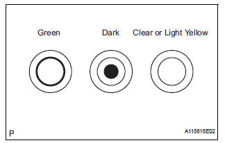
(a) Check the color of the hydrometer.
Result 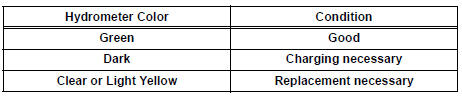
3. CHECK BATTERY VOLTAGE
(a) If it has not been 20 minutes since the vehicle was driven or since the engine was stopped, turn the ignition switch to the ON position and turn on the electrical systems (headlights, blower motor, rear defogger, etc.) for 60 seconds. This will remove the surface charge from the battery.
(b) Turn the ignition switch off and the electrical systems off.
(c) Measure the battery voltage between the negative (- ) and positive (+) terminals of the battery.
Standard voltage: 12.5 to 12.9 V at 20°C (68°F)
HINT: If the voltage is below the specification, charge the battery.
4. CHECK BATTERY TERMINAL
(a) Check that the battery terminals are not loose or corroded.
If the terminals are corroded, clean them.
5. CHECK FUSES
(a) Measure the resistance of the ALT fuse, ALT-S fuse, GAUGE fuse and GAUGE 1 fuse.
Standard resistance: Below 1 Ω
If the result is not as specified, replace the fuses as necessary.
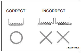
6. CHECK V-RIBBED BELT
(a) Check the belt for wear, cracks or other signs of damage.
If any of the following defects is found, replace the V-ribbed belt.
- The belt is worn out, cracked, or the cords are exposed.
- The cracks reach the cords in more than one place.
- The belt has chunks missing from the ribs.
(b) Check that the belt fits properly in the ribbed grooves.
HINT:
Check with your hand to confirm that the belt has not slipped out of the groove on the bottom of the pulley.
If it has slipped out, replace the V-ribbed belt. Install a new V-ribbed belt correctly.
7. INSPECT GENERATOR WIRING
(a) Visually check the generator wiring.
(1) Check that the wiring is in good condition.
8. CHECK FOR ABNORMAL NOISES
(a) Listen for abnormal noises from the generator.
(1) Check that no abnormal noises are heard from the generator while the engine is running.
9. CHECK CHARGE WARNING LIGHT CIRCUIT
(a) Turn the ignition switch to the ON position. Check that the charge warning light comes on.
(b) Start the engine and check that the light goes off.
If the light does not operate as specified, troubleshoot the charge warning light circuit.
10. INSPECT CHARGING CIRCUIT WITHOUT LOAD
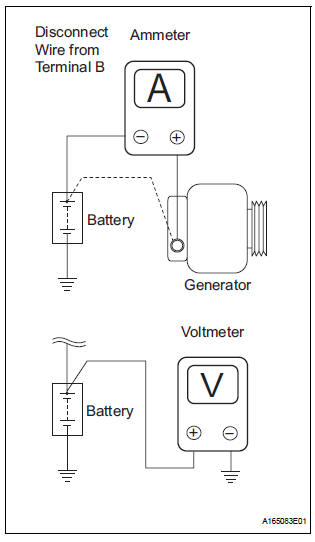
(a) Connect a voltmeter and ammeter to the charging circuit as follows.
(1) Disconnect the wire from terminal B of the generator, then connect it to the negative (-) lead of an ammeter.
(2) Connect the positive (+) lead of the ammeter to terminal B of the generator.
(3) Connect the positive (+) lead of a voltmeter to positive (+) terminal of the battery.
(4) Ground the negative (-) lead of the voltmeter.
(b) Check the charging circuit.
(1) Keep the engine speed at 2000 rpm and check the reading on the ammeter and voltmeter.
Standard amperage: 10 A or less
Standard voltage: 13.2 to 14.8 V
If the result is not as specified, replace the generator.
HINT: If the battery is not fully charged, the ammeter reading will sometimes be more than the standard amperage.
11. INSPECT CHARGING CIRCUIT WITH LOAD
(a) Keep the engine speed at 2000 rpm, turn on the high beam headlights, and turn the heater blower switch to the "HI" position.
(b) Check the reading on the ammeter.
Standard amperage: 30 A or more
If the ammeter reading is less than the standard amperage, replace the generator assembly.
HINT: If the battery is fully charged, the ammeter reading may be less than the standard amperage. In this case, increase electrical load by operating devices such as the wiper motor and rear window defogger.
Then, recheck the reading on the ammeter.
 Precaution
1. Check that the battery cables are connected to the
correct terminals.
2. Disconnect the battery cables when the battery is
given a quick charge.
3. Do not perform tests with a high voltage ...
 Charge Warning Light Comes ON while Driving
INSPECTION PROCEDURE
1 CHECK LOCK FUNCTION OF CLUTCH PULLEY
(a) Check the lock function with the pulley installed in the
vehicle.
(1) Visually check that the rotor in the generator
operates wit ...
Other materials:
ACIS Control Circuit
DESCRIPTION
This circuit opens and closes the Intake Air Control Valve (IACV) in response
to changes in the engine
load in order to increase the intake efficiency (ACIS: Acoustic Control
Induction System).
When the engine speed is between 0 and 4450 rpm and the throttle valve opening
angl ...
Installation
1. INSTALL REAR DOOR WINDOW FRAME MOULDING
Remove the tape from the rear door window frame
moulding.
Clean the contact surface of the vehicle body with
white gasoline.
Clean the outer circumference of the rear door
window frame moulding with white gasoline.
Apply new double-sided ...
Using the rear view monitor system
Screen description
The rear view monitor system screen will be displayed if the shift
lever is shifted to R while the engine switch is in the “ON” position
(vehicles without a smart key system) or IGNITION ON mode (vehicles
with a smart key system).
Vehicle width guide line
The lin ...
