Toyota Sienna Service Manual: Problem symptoms table
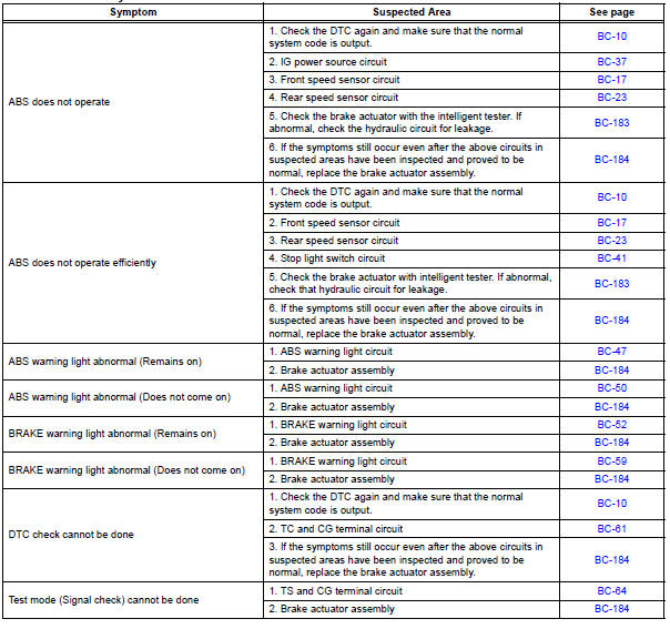
If there are no DTCs output but the problem still occurs, check the circuits for each problem symptom in the order given in the table below and proceed to the relevant troubleshooting page.
NOTICE: When replacing the brake actuator assembly, sensor, etc., turn the ignition switch off.
HINT: Inspect the fuse and relay before investigating the suspected areas as shown in the table below. Inspect each malfunction circuit in numerical order for the corresponding symptom.
Anti-lock brake system:
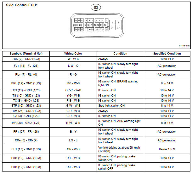
Terminals of ecu
 Test mode procedure
1. SPEED SENSOR SIGNAL CHECK (WHEN USING SST CHECK WIRE):
HINT:
If the ignition switch is turned from the ON to the ACC
or LOCK position during Test Mode, the DTCs of the
signal check functio ...
 Diagnosis system
1. DESCRIPTION
(a) Release the parking brake pedal.
(b) Check the warning lights.
When ignition switch is turned ON, check that the
ABS warning light and brake warning light come on
for 3 ...
Other materials:
Intake Air Temperature Circuit/ Intake Air Temperature Circuit Low Input/
Intake Air Temperature Circuit High Input
DTC P0110 Intake Air Temperature Circuit
DTC P0112 Intake Air Temperature Circuit Low Input
DTC P0113 Intake Air Temperature Circuit High Input
DESCRIPTION
The Intake Air Temperature (IAT) sensor, mounted on the Mass Air Flow (MAF)
meter, monitors the IAT.
The IAT sensor has a built-in ther ...
If your vehicle overheats
The following may indicate that your vehicle is overheating.
The needle of the engine coolant temperature gauge
enters the red zone or a loss of engine power is experienced. (For
example, the vehicle speed does not increase.)
The warning message indicating overheats is shown on the
mult ...
Short to B+ in Rear Curtain Shield Squib RH
Circuit
DTC B1633/82 Short to B+ in Rear Curtain Shield Squib RH
Circuit
DESCRIPTION
The rear curtain shield squib RH circuit consists of the center airbag sensor
assembly and the curtain
shield airbag assembly RH.
The circuit instructs the SRS to deploy when deployment conditions are met.
DTC B ...
