Toyota Sienna Service Manual: Rear Air Mix Damper Position Sensor Circuit
DESCRIPTION
This sensor detects the position of the rear air mix control servo motor (water valve servo motor) and sends the appropriate signals to the A/C amplifier. The position sensor is built in the rear air mix control servo motor (water valve servo motor).
The position sensor's resistance changes as the rear air mix control servo motor valve moves.
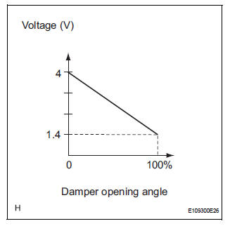
It outputs voltage (5 V) that is input to terminal 2 and terminal 3 via the variable resistor, and then to the A/ C amplifier.
The A/C amplifier determines the valve position based on the input voltage from
the position sensor.
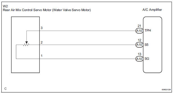
WIRING DIAGRAM
INSPECTION PROCEDURE
1 READ VALUE OF INTELLIGENT TESTER
(a) Connect the intelligent tester to the DLC3.
(b) Turn the ignition switch to the ON position and turn the intelligent tester main switch on.
(c) Select the items below in the DATA LIST, and read the display on the intelligent tester.
DATA LIST / AIR CONDITIONER 
OK: The display is as specified in the normal condition column.
Result 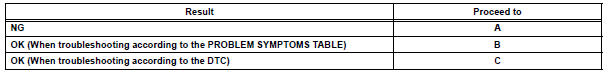

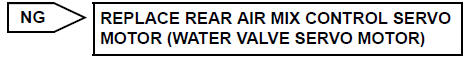
2 INSPECT REAR AIR MIX CONTROL SERVO MOTOR (WATER VALVE SERVO MOTOR)
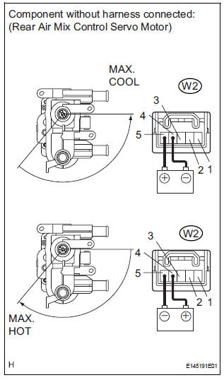
(a) Remove the rear air mix control servo motor (water valve servo motor).
(b) Disconnect the connector from the rear air mix control servo motor (water valve servo motor).
(c) Measure the resistance according to the value(s) in the table below.
Standard resistance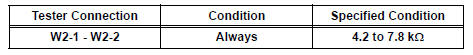
(d) Measure the resistance according to the value(s) in the table below.
HINT
- In order to turn the motor to the "MAX. COOL" position, connect the positive (+) lead to terminal 5, and the negative (-) lead to terminal 4.
- In order to turn the motor to the "MAX. HOT" position, connect the positive (+) lead to terminal 4, and the negative (-) lead to terminal 5.
Standard resistance 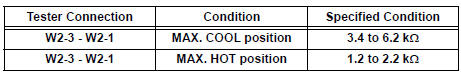
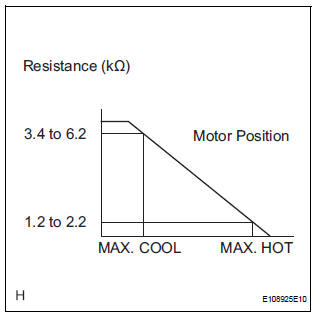
(e) As the rear air mix control servo motor (water valve servo motor) moves from the cool side to the hot side, the resistance decreases gradually without interruption.

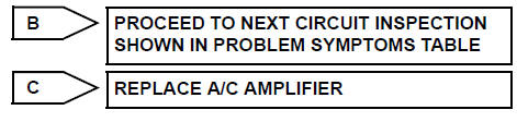
3 CHECK HARNESS AND CONNECTOR (REAR AIR MIX CONTROL SERVO MOTOR - A/C AMPLIFIER)
(a) Disconnect the connector from the A/C amplifier.
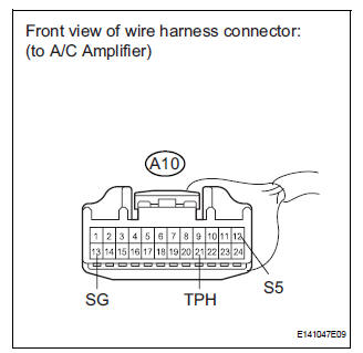
(b) Measure the resistance according to the value(s) in the table below.
Standard resistance 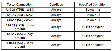

REPLACE A/C AMPLIFIER
 Air Mix Damper Position Sensor Circuit (Driver Side)
DESCRIPTION
This sensor detects the position of the air mix control servo motor (air
outlet damper) and sends the
appropriate signals to the A/C amplifier. The position sensor is built in the ...
 Rear Air Outlet Damper Position Sensor Circuit
DESCRIPTION
This sensor detects the position of the rear air outlet control servo motor
and sends the appropriate
signals to the A/C amplifier. The position sensor is built in the rear air
o ...
Other materials:
Open in ABS Motor Relay Circuit
DESCRIPTION
The ABS motor relay supplies power to the ABS pump motor. While the ABS is
activated, the ECU turns
the motor relay on and operates the ABS pump motor.
If the voltage supplied to the motor relay (+BM) is below the DTCs detection
threshold due to low voltage
from the battery ...
Folding down the third seats (power seats)
You can operate the power third seats when the shift lever is in P.
Before folding the third seats
Lower the center head
restraint to the lowest position and stow the
seat belt buckles.
Stow the center seat belt.
Folding down the third seatbacks
Press the folding/returning ...
Changing the vehicle-to-vehicle distance
Pressing the button changes the
vehicle-to-vehicle distance as follows:
Long
Medium
Short
The vehicle-to-vehicle distance is
set automatically to long mode
when the engine switch is turned to
IGNITION ON mode.
If a vehicle is running ahead of
you, the preceding vehicle mark
w ...
