Toyota Sienna Service Manual: Rear Airbag Sensor LH Circuit Malfunction
DTC B1155/39 Rear Airbag Sensor LH Circuit Malfunction
DESCRIPTION
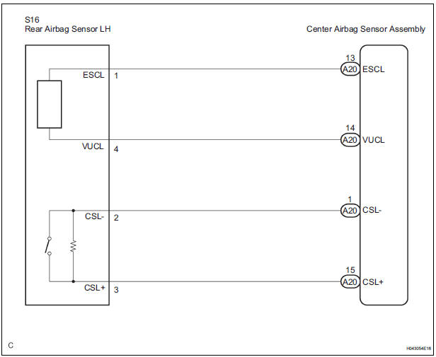
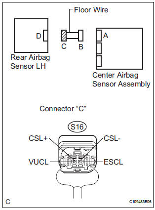
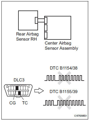
The rear airbag sensor LH circuit consists of the center airbag sensor assembly and rear airbag sensor LH.
If the center airbag sensor assembly receives signals from the rear airbag sensor LH, it judges whether or not the SRS should be activated.
DTC B1155/39 is recorded when a malfunction is detected in the rear airbag sensor LH circui
|
DTC No. |
DTC Detecting Condition |
Trouble Area |
|
B1155/39 |
|
|
WIRING DIAGRAM
INSPECTION PROCEDURE
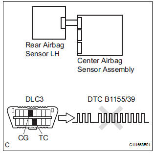
1 CHECK DTC
- Turn the ignition switch to the ON position, and wait for at least 60 seconds.
- Clear the DTCs stored in memory (5).
- Turn the ignition switch to the LOCK position.
- Turn the ignition switch to the ON position, and wait for at least 60 seconds.
- Check the DTCs (5).
OK: DTC B1155/39 is not output.
HINT: Codes other than code B1155/39 may be output at this time, but they are not related to this check.
 Go to step 2

USE SIMULATION METHOD TO CHECK
2 CHECK CONNECTION OF CONNECTORS
- Turn the ignition switch to the LOCK position.
- Disconnect the negative (-) terminal cable from the battery, and wait for at least 90 seconds.
- Check that the connectors are properly connected to the center airbag sensor assembly and the rear airbag sensor LH.
OK: The connectors are connected.
 CONNECT CONNECTORS

3 CHECK FLOOR WIRE (OPEN)
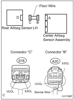
- Disconnect the connectors from the center airbag sensor assembly and the rear airbag sensor LH.
- Using a service wire, connect A20-14 (VUCL) and A20-
13 (ESCL) of connector "B".
NOTICE: Do not forcibly insert a service wire into the terminals of the connector when connecting.
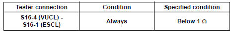
- Measure the resistance according to the value(s) in the table below.
Standard resistance
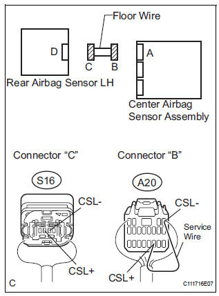
- Using a service wire, connect A20-15 (CSL+) and A20-1
(CSL-) of connector "B".
NOTICE: Do not forcibly insert a service wire into the terminals of the connector when connecting.
- Measure the resistance according to the value(s) in the table below.
Standard resistance
 REPAIR OR REPLACE FLOOR WIRE

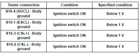
4 CHECK FLOOR WIRE (SHORT TO B+)
- Disconnect SST from connector "B".
- Connect the negative (-) terminal cable to the battery, and wait for at least 2 seconds.
- Turn the ignition switch to the ON position.
- Measure the voltage according to the value(s) in the table below.
Standard voltage
 REPAIR OR REPLACE FLOOR WIRE

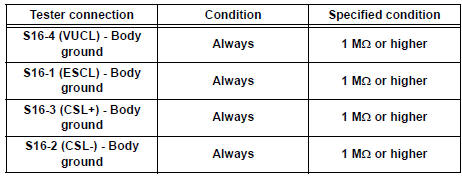
5 CHECK FLOOR WIRE (SHORT TO GROUND)
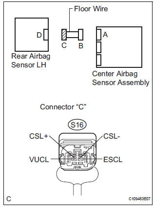
- Turn the ignition switch to the LOCK position.
- Disconnect the negative (-) terminal cable from the battery, and wait for at least 90 seconds.
- Measure the resistance according to the value(s) in the table below.
Standard resistance
 REPAIR OR REPLACE FLOOR WIRE

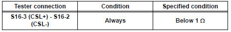
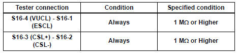
6 CHECK FLOOR WIRE (SHORT)
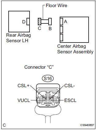
- Measure the resistance according to the value(s) in the table below.
Standard resistance
 REPAIR OR REPLACE FLOOR WIRE

7 CHECK REAR AIRBAG SENSOR LH
- Connect the connector to the center airbag sensor assembly.
- Interchange the rear airbag sensor RH with LH and connect the connectors to them.
- Connect the negative (-) terminal cable to the battery, and wait for at least 2 seconds.
- Turn the ignition switch to the ON position, and wait for at least 60 seconds.
- Clear the DTCs stored in memory (5).
- Turn the ignition switch to the LOCK position.
- Turn the ignition switch to the ON position, and wait for at least 60 seconds.
- Check the DTCs (5).
Result
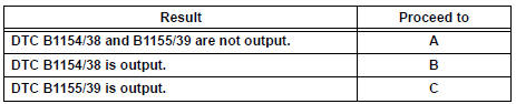
HINT: Codes other than DTC B1154/38 and B1155/39 may be output at this time, but they are not related to this check.
 REPLACE REAR AIRBAG SENSOR LH
 REPLACE CENTER AIRBAG SENSOR
ASSEMBLY
REPLACE CENTER AIRBAG SENSOR
ASSEMBLY

USE SIMULATION METHOD TO CHECK
 Rear Airbag Sensor RH Circuit Malfunction
DTC B1154/38 Rear Airbag Sensor RH Circuit Malfunction
DESCRIPTION
The rear airbag sensor RH circuit consists of the center airbag sensor
assembly and rear airbag sensor
RH.
If the center airb ...
 Short in Curtain Shield Squib RH Circuit
DTC B1160/83 Short in Curtain Shield Squib RH Circuit
DESCRIPTION
The curtain shield squib RH circuit consists of the center airbag sensor
assembly and the curtain shield
airbag assembly RH.
T ...
Other materials:
Outer mirror switch
Inspection
1. INSPECT OUTER MIRROR SWITCH ASSEMBLY (w/o
Memory)
The L side of the left / right adjustment switch:
Inspect the mirror switch resistance.
Standard resistance (Left side)
If the result is not as specified, replace the switch
assembly.
The R side of t ...
Short in Driver Side Squib 2nd Step Circuit
DTC B1180/17 Short in Driver Side Squib 2nd Step Circuit
DESCRIPTION
The driver side squib 2nd step circuit consists of the center airbag sensor
assembly, the spiral cable and
the steering pad.
The circuit instructs the SRS to deploy when deployment conditions are met.
DTC B1180/17 is rec ...
Open in Rear Curtain Shield Squib RH Circuit
DTC B1631/84 Open in Rear Curtain Shield Squib RH Circuit
DESCRIPTION
The rear curtain shield squib RH circuit consists of the center airbag sensor
assembly and the curtain
shield airbag assembly RH.
The circuit instructs the SRS to deploy when deployment conditions are met.
DTC B1631/84 ...
