Toyota Sienna Service Manual: Removal
1. DISCONNECT CABLE FROM NEGATIVE BATTERY TERMINAL
2. REMOVE REAR NO. 2 SEAT LEG SIDE GARNISH SUB-ASSEMBLY
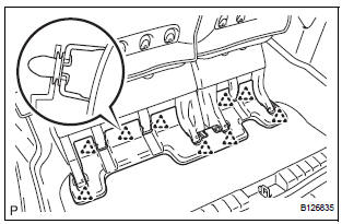
- Disengage the 9 clips and remove the rear No. 2 seat leg side garnish sub-assembly.
- Remove the 9 clips from the rear No. 2 seat leg side garnish sub-assembly.
3. REMOVE REAR SEAT LEG SIDE GARNISH SUBASSEMBLY
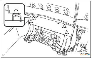
- Disengage the 4 clips and remove the rear seat leg side garnish sub-assembly.
- Remove the 4 clips from the rear seat leg side garnish sub-assembly.
4. REMOVE NO. 2 SEAT HINGE COVER
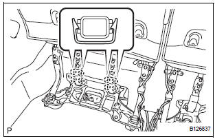
- Disengage the 8 claws and remove both No. 2 seat hinge covers.
5. REMOVE REAR NO. 2 SEAT ASSEMBLY
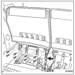
- Disconnect the connector.
- Remove the 8 bolts.
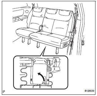
- Pull the lever under the No. 2 seat cushion subassembly and remove the rear No. 2 seat assembly.
 Rear no. 2 Seat assembly (for Power Seat Type LH Side)
COMPONENTS
...
 Disassembly
1. REMOVE REAR NO. 2 SEAT COVER BEZEL
Remove the 5 screws.
Disengage the 5 claws and remove the rear No. 2
seat cover bezel.
2. REMOVE REAR SEAT RECLINING COVER LH
& ...
Other materials:
Stowing the spare tire
Lay down the tire with the outer
side (valve stem) facing up, and
install the holding bracket.
Turn the jack handle clockwise
to raise the tire until the tire is in
the correct position as the jack
handle skips.
Stow the tools.
The compact spare tire
The compact s ...
Disassembly
1. REMOVE RADIATOR WATER INLET
(a) Remove the 2 bolts and radiator water inlet.
2. REMOVE DRAIN PLUG
(a) Remove the drain plug and air drain plug.
(b) Remove the 2 O-rings.
3. REMOVE LOWER RADIATOR TANK
(a) Install the claw to the overhaul handle, inserting it in
the hole in Part A ...
Wireless remote control/
electronic key battery
Replace the battery with a new one if it is depleted.
You will need the following items:
Flathead screwdriver
Lithium battery CR2032
Replacing the battery
Vehicles without a smart key system
Remove the cover using a coin
protected with tape etc.
Remove the deplete ...
