Toyota Sienna Service Manual: No. 1 Speaker with box
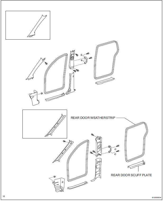
COMPONENTS
ON-VEHICLE INSPECTION
1. INSPECT NO.1 SPEAKER WITH BOX
HINT: Remove interior parts so that the No.1 speaker with box can be seen.
- Check the speaker installation.
OK: The speaker is securely installed.
If the result is not as specified, reinstall the No.1 speaker with box.
- Visually check the speaker.
OK: The cone paper of the speaker is not torn.
If the result is not as specified, replace the No.1 speaker with box.
REMOVAL
1. REMOVE REAR DOOR SCUFF PLATE
2. REMOVE REAR DOOR WEATHERSTRIP
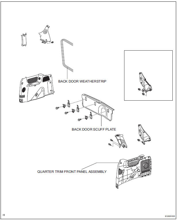
3. REMOVE BACK DOOR WEATHERSTRIP
4. REMOVE BACK DOOR SCUFF PLATE
5. REMOVE QUARTER TRIM FRONT PANEL ASSEMBLY
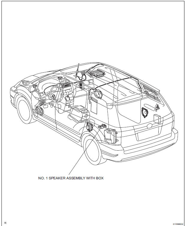
6. REMOVE NO. 1 SPEAKER ASSEMBLY WITH BOX
- Remove the 2 screws and No. 1 speaker assembly with box.
INSTALLATION
1. INSTALL NO. 1 SPEAKER ASSEMBLY WITH BOX
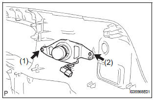
- Install the No. 1 speaker assembly with box with the 2 screws.
NOTICE: Tighten the screws in order shown in the illustration to install the No. 1 speaker assembly with box.
2. INSTALL QUARTER TRIM FRONT PANEL ASSEMBLY
3. INSTALL BACK DOOR SCUFF PLATE
4. INSTALL BACK DOOR WEATHERSTRIP
5. INSTALL REAR DOOR WEATHERSTRIP
6. INSTALL REAR DOOR SCUFF PLATE
 Rear speaker
COMPONENTS
ON-VEHICLE INSPECTION
1. INSPECT REAR SPEAKER
HINT:
Remove interior parts so that the rear speaker can be
seen.
Check the speaker installation.
OK:
The speaker is ...
 No. 2 Speaker with box
COMPONENTS
ON-VEHICLE INSPECTION
1. INSPECT NO.2 SPEAKER WITH BOX
HINT:
Remove interior parts so that the No.2 speaker with box
can be seen.
Check the speaker installation.
OK ...
Other materials:
Installation
1. REMOVE FRONT SEAT INNER BELT ASSEMBLY
HINT:
Refer to the instructions for reassembly of the front seat assembly
(for flat type).
Refer to the instructions for reassembly of the front seat assembly
(for manual seat).
Refer to the instructions for reassembly of the ...
Engine Control System Malfunction
DTC C1201/51 Engine Control System Malfunction
DESCRIPTION
If trouble occurs the engine control system, the ECM transmits the
abnormality to the skid control ECU.
The skid control ECU set this DTC and the skid control ECU prohibits TRAC and
VSC control.
INSPECTION PROCEDURE
1 CHECK ENGIN ...
Removal
HINT:
On the RH side, use the same procedures as on the LH side.
1. REMOVE SLIDE DOOR
Remove the rear door scuff plate (See page IR-7).
Remove the back door scuff plate (See page ED-
214).
Remove the quarter trim panel (See page IR-9).
Remove the upper rail cushion from the rail up ...
