
Toyota Sienna Service Manual: Stereo component speaker
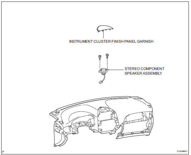
COMPONENTS
ON-VEHICLE INSPECTION
1. INSPECT STEREO COMPONENT SPEAKER
HINT: Remove interior parts so that the stereo component speaker can be seen.
- Check the speaker installation.
OK: The speaker is securely installed.
If the result is not as specified, reinstall the stereo component speaker speaker.
- Visually check the speaker.
OK: The cone paper of the speaker is not torn.
If the result is not as specified, replace the stereo component speaker speaker.
- Speaker resistance check
- Disconnect the stereo component speaker speaker connector.
- Measure the resistance between the terminals of the speaker.
Standard resistance: 1.2 to 2.2 Ω
If the result is not as specified, replace the stereo component speaker speaker.
REMOVAL
1. REMOVE INSTRUMENT CLUSTER FINISH PANEL GARNISH
2. REMOVE STEREO COMPONENT SPEAKER ASSEMBLY
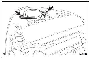
- Remove the 2 screws.
- Disconnect the connector and remove the stereo component speaker assembly.
INSTALLATION
1. INSTALL STEREO COMPONENT SPEAKER ASSEMBLY
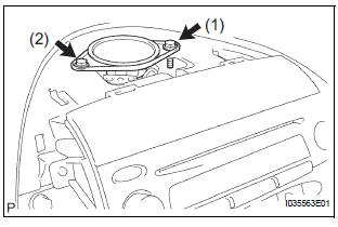
- Connect the connector.
- Install the stereo component speaker assembly with the 2 screws.
NOTICE: Tighten the screws in order shown in the illustration to install the stereo component speaker assembly.
2. INSTALL INSTRUMENT CLUSTER FINISH PANEL GARNISH
 Front No. 2 speaker
COMPONENTS
ON-VEHICLE INSPECTION
1. INSPECT FRONT NO.2 SPEAKER
HINT:
Remove interior parts so that the front No.2 speaker can
be seen.
Check the speaker installation.
OK:
The sp ...
 Rear speaker
COMPONENTS
ON-VEHICLE INSPECTION
1. INSPECT REAR SPEAKER
HINT:
Remove interior parts so that the rear speaker can be
seen.
Check the speaker installation.
OK:
The speaker is ...
Other materials:
Communication Error from VSC to ECM
DTC P1630 Communication Error from VSC to ECM
DTC U0122 Lost Communication with Vehicle Dynamics
Control Module
DESCRIPTION
The skid control ECU sends signals such as cruise control cancel demand
signals and brake operation
demand (from ECM) response signals to the ECM when the dynamic laser ...
Security Horn Circuit
DESCRIPTION
During the alarm sounding state, the relay in the ECU turns on and off in a
cycle of approximately 0.2
seconds, causing the security horn to sound.
WIRING DIAGRAM
INSPECTION PROCEDURE
1 INSPECT SECURITY HORN ASSEMBLY
Disconnect the T1 security horn connector.
C ...
SFR Solenoid Circuit
DESCRIPTION
The solenoid comes on when signals are received from the ECU and controls the
pressure acting on the
wheel cylinders, thus controlling brake force.
WIRING DIAGRAM
INSPECTION PROCEDURE
1 RECONFIRM DTC
HINT:
These codes are detected when a problem is identified in the
...
