Toyota Sienna Service Manual: Vehicle Speed Signal Circuit between Multi-display and Combination Meter
DESCRIPTION
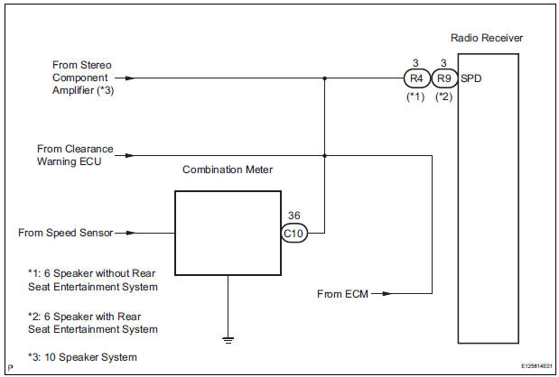
This circuit is necessary for the ASL (Auto Sound Leveliser) built into the radio receiver.
Speed signals are received from the combination meter and used for the ASL.
The ASL function automatically adjusts the sound data in order to enable hearing the clear audio sound even when vehicle noise increases (as vehicle noise increases, the volume is turned up etc.).
HINT:
- A voltage of 12 V or 5 V is output from each ECU and then input to the combination meter. The signal is changed to a pulse signal at the transistor in the combination meter. Each ECU controls the respective system based on the pulse signal.
- If a short occurs in an ECU, all systems in the diagram below will not operate normally.
WIRING DIAGRAM
INSPECTION PROCEDURE
1 CHECK OPERATION OF SPEEDOMETER
- Drive the vehicle and check if the function of the speedometer on the combination meter is normal
OK: Actual vehicle speed and the speed indicated on the speedometer are the same.
HINT: The vehicle speed sensor is functioning normally when the indication on the speedometer is normal.
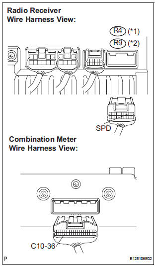
2 INSPECT RADIO RECEIVER
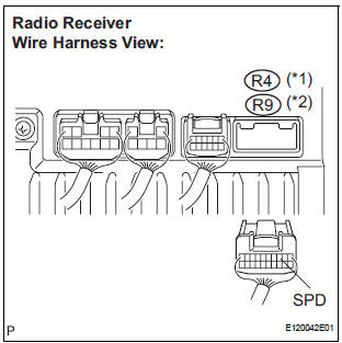
- Disconnect the radio receiver connector.
- Measure the voltage.
- Jack up either one of the drive wheels.
- Move the shift lever to the neutral position.
- Turn the ignition switch to the ON position.
*1: 6 Speaker without Rear Seat Entertainment System.
*2: 6 Speaker with Rear Seat Entertainment System
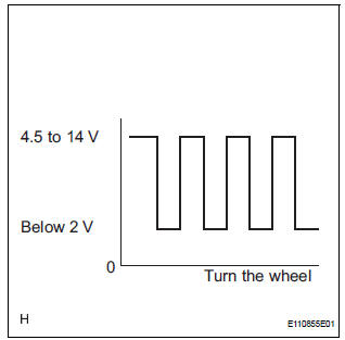
- Measure the voltage between terminal SPD of the radio receiver and body ground when the drive wheels are turned slowly.
OK: Voltage pulses as shown in the illustration.
REPLACE RADIO RECEIVER
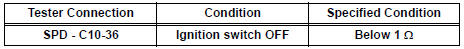
3 CHECK HARNESS AND CONNECTOR (COMBINATION METER - RADIO RECEIVER)
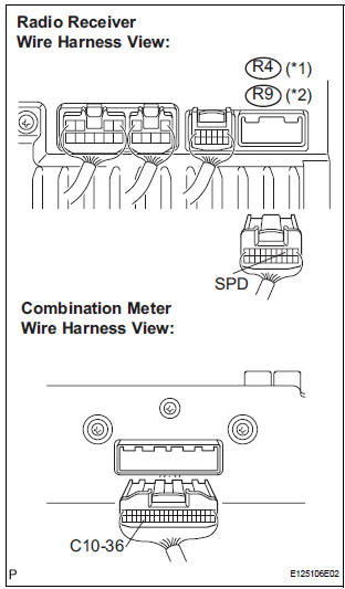
- Disconnect the radio receiver connector and combination meter connector.
- Measure the resistance according to the value(s) in the table below.
Standard resistance
*1: 6 Speaker without Rear Seat Entertainment System.
*2: 6 Speaker with Rear Seat Entertainment System.
4 CHECK HARNESS AND CONNECTOR (COMBINATION METER - RADIO RECEIVER)
- Disconnect the radio receiver connector and combination meter connector.
- Measure the resistance according to the value(s) in the table below.
Standard resistance
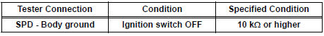
HINT: If the resistance between terminal SPD and body ground is less than 10 kΩ, there may be a short in a wire harness, connector, or an ECU that is connected to the SPD signal wire.
*1: 6 Speaker without Rear Seat Entertainment System.
*2: 6 Speaker with Rear Seat Entertainment System.
REPLACE COMBINATION METER
 AVC-LAN Circuit
DESCRIPTION
Each unit of the audio system connected to the AVC-LAN (communication bus)
transfers the signal of
each switch by communication.
When a short to +B or short to ground occurs in this ...
 Vehicle Speed Signal Circuit between Stereo Component Amplifier and
Combination Meter
Vehicle Speed Signal Circuit between Stereo Component Amplifier and
Combination Meter
DESCRIPTION
This circuit is necessary for the ASL (Auto Sound Leveliser) built into the
stereo component amplifier.
Speed signals are received from the combination meter and used for the ASL.
...
Other materials:
If the battery is
discharged
The following procedures may be used to start the engine if the
vehicle’s battery is discharged.
You can call your Toyota dealer or qualified repair shop.
If you have a set of jumper (or booster) cables and a second vehicle
with a 12-volt battery, you can jump start your vehicle by following ...
Air Outlet Damper Control Servo Motor Circuit
DESCRIPTION
This circuit turns the servo motor and changes each damper position by
receiving the signals from the A/
C amplifier.
The air outlet damper servo motor switches the air outlet mode by rotating
(normal, reverse) with electrical
power from the A/C amplifier.
When the AUTO swit ...
TC and CG Terminal Circuit
DESCRIPTION
DTC output mode is set by connecting terminals TC and CG of the DLC3.
The DTCs are displayed by the blinking pattern of the ABS warning light.
WIRING DIAGRAM
HINT:
When warning lights continue to blink, a ground short in the wiring of terminal
TC of the DLC3 or an
internal ...
