Toyota Sienna Service Manual: ABS Warning Light Remains ON
DESCRIPTION
If any of the following is detected, the ABS warning light remains on.
- The skid control ECU connectors are disconnected from the skid control ECU.
- There is a malfunction in the skid control ECU internal circuit.
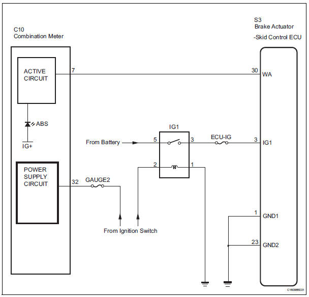
- There is an open in the harness between the combination meter and the skid control ECU.
HINT: In some cases, the intelligent tester cannot be used when the skid control ECU is abnormal.
WIRING DIAGRAM
INSPECTION PROCEDURE
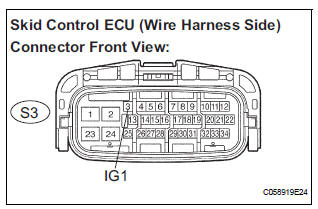
1 INSPECT SKID CONTROL ECU CONNECTOR IS SECURELY CONNECTED
(a) Check the skid control ECU connector's connecting condition.
OK: The connector should be securely connected.

2 INSPECT BATTERY
(a) Check the battery voltage.
Standard voltage: 11 to 14 V

2 INSPECT BATTERY
(a) Check the battery voltage.
Standard voltage: 11 to 14 V


3 INSPECT SKID CONTROL ECU (IG1 TERMINAL VOLTAGE)
(a) Disconnect the skid control ECU connector.
(b) Turn the ignition switch to the ON position.
(c) Measure the voltage according to the value(s) in the table below.
Standard voltage 

4 INSPECT SKID CONTROL ECU (GND TERMINAL CONTINUITY)
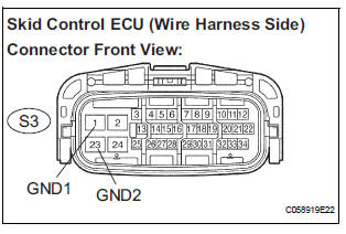
(a) Turn the ignition switch off.
(b) Measure the resistance according to the value(s) in the table below.
Standard resistance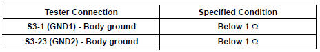

5 CHECK HARNESS AND CONNECTOR (BETWEEN SKID CONTROL ECU AND COMBINATION METER ASSEMBLY)
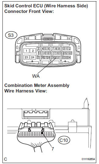
(a) Disconnect the combination meter connector.
(b) Measure the resistance according to the value(s) in the table below.
Standard resistance 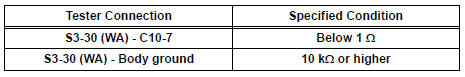

6 INSPECT COMBINATION METER ASSEMBLY
(a) Check the combination meter (See page ME-4).
HINT: If troubleshooting has been carried out according to the PROBLEM SYMPTOMS TABLE, refer back to the table and proceed to the next step before replacing the part (See page BC-7).

REPLACE BRAKE ACTUATOR ASSEMBLY
 Open in Pump Motor Circuit
DTC C1251/51 Open in Pump Motor Circuit
DESCRIPTION
The motor relay (semiconductor relay) is housed in the brake actuator
assembly and drives the pump
motor based on a signal from the skid contro ...
 ABS Warning Light does not Come ON
WIRING DIAGRAM
See page BC-47.
INSPECTION PROCEDURE
1 INSPECT ABS WARNING LIGHT
(a) Disconnect the skid control ECU connector.
(b) Turn the ignition switch to the ON position.
(c) Check that ...
Other materials:
Basic inspection
When a malfunction is not confirmed by the DTC check,
troubleshooting should be carried out in all circuits
considered to be possible causes of the problem. In many
cases, by carrying out the basic engine check shown in the
following flowchart, the location of the problem can be found
quickly a ...
Front Occupant Classification Sensor LH Collision
Detection
DTC B1785 Front Occupant Classification Sensor LH Collision
Detection
DESCRIPTION
DTC B1785 is output when the occupant classification ECU receives a collision
detection signal sent by
the front occupant classification sensor LH if an accident occurs.
DTC B1785 is also output when the front ...
Open in Front Passenger Side Squib 2nd Step
Circuit
DTC B1186/58 Open in Front Passenger Side Squib 2nd Step
Circuit
DESCRIPTION
The front passenger side squib 2nd step circuit consists of the center airbag
sensor assembly and the
front passenger airbag assembly.
The circuit instructs the SRS to deploy when deployment conditions are met.
...
