Toyota Sienna Service Manual: Reassembly
1. INSTALL HEATER RADIATOR UNIT SUB-ASSEMBLY
(a) Install the heater radiator unit sub-assembly to the air conditioning blower assembly.
(b) Install the 2 O-rings to the heater water valve assembly.
(c) Install the 3 screws and the heater water valve assembly.
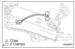
(d) Install the 2 screws and the 2 clamps.
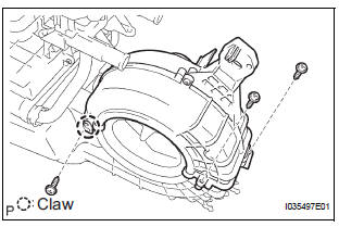
(e) Engage the claw fitting and install the 3 screws and blower case.
2. INSTALL BLOWER RESISTOR TRANSISTOR ASSEMBLY
(a) Install the 2 screws and the blower resistor transistor assembly.
3. INSTALL COOLING UNIT MOTOR SUB-ASSEMBLY WITH FAN
(a) Install the 3 screws and the cooling unit motor subassembly w/ fan.
 Disassembly
1. REMOVE COOLER THERMISTOR NO.1 (for Automatic Air Conditioning System)
(a) Disengage the 2 claw fittings and the clamp and
remove the cooler thermistor No. 1.
2. REMOVE COOLING UNIT MOTOR SUB ...
 Installation
1. INSTALL AIR CONDITIONING BLOWER ASSEMBLY
(a) Install the air conditioning blower assembly with the
3 bolts.
Torque: 5.4 N*m (55 kgf*cm, 48 in.*lbf)
NOTICE:
Tighten the bolts in the order s ...
Other materials:
Brake Switch "A" Circuit
DTC P0571 Brake Switch "A" Circuit
DESCRIPTION
When the brake pedal is depressed, the stop light switch sends a signal to
the ECM. When the ECM
receives this signal, it cancels the cruise control. The fail-safe function
operates to enable normal driving
even if there is a malfuncti ...
Turn signal light switch
ON-VEHICLE INSPECTION
1. INSPECT TURN SIGNAL FLASHER CIRCUIT
Measure voltage between the terminals as shown in
the chart below.
Voltage
Connect the connector to turn the signal flasher and
turn the ignition switch ON, and inspect the wire
harness side connector from t ...
Chassis
GENERAL MAINTENANCE
1. INSPECT STEERING LINKAGE
(a) Check the steering linkage for looseness or
damage.
Check that:
Tie rod ends do not have excessive play.
Dust seals and boots are not damaged.
Boot clamps are not loose.
(b) Inspect the dust cover for damage.
2. INSPECT STEERING G ...
