Toyota Sienna Service Manual: Disassembly
1. REMOVE COOLER THERMISTOR NO.1 (for Automatic Air Conditioning System)
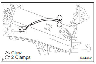
(a) Disengage the 2 claw fittings and the clamp and remove the cooler thermistor No. 1.
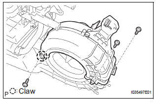
2. REMOVE COOLING UNIT MOTOR SUB-ASSEMBLY WITH FAN
(a) Remove the 3 screws and the cooling unit motor sub-assembly w/ fan.
3. REMOVE BLOWER RESISTOR TRANSISTOR ASSEMBLY
(a) Remove the 2 screws and the blower resistor transistor assembly.
4. REMOVE HEATER RADIATOR UNIT SUB-ASSEMBLY
(a) Disengage the claw fitting and remove the 3 screws and blower case.
(b) Remove the 2 screws and the 2 clamps.
(c) Remove the 3 screws and the heater water valve assembly.
(d) Remove the 2 O-rings from the heater water valve assembly.
(e) Remove the heater radiator unit sub-assembly from the air conditioning blower assembly.
 Removal
1. DISCHARGE REFRIGERANT FROM
REFRIGERATION SYSTEM
SST 07110-58060 (07117-58080, 07117-58090,
07117-78050, 07117-88060, 07117-88070,
07117-88080)
HINT:
See page AC-172.
2. REMOVE REAR DOOR SCUF ...
 Reassembly
1. INSTALL HEATER RADIATOR UNIT SUB-ASSEMBLY
(a) Install the heater radiator unit sub-assembly to the
air conditioning blower assembly.
(b) Install the 2 O-rings to the heater water valve
as ...
Other materials:
Seat heaters
For driver’s seat
For front passenger’s seat
On
The indicator light comes on.
Adjusts the seat temperature
The further you move the dial
upward, the warmer the seat
becomes.
The seat heaters can be used when the engine switch is in the “ON”
position
(vehicles ...
Vehicle Speed Sensor Malfunction
DTC P0500 Vehicle Speed Sensor Malfunction
DTC P0503 Vehicle Speed Sensor Circuit Malfunction
DESCRIPTION
The cruise control system uses the same vehicle speed signal that is sent to
the ECM for the SFI system.
If DTC P0500 is detected, perform the diagnosis using the inspection procedure
...
Low Battery Positive Voltage
DTC C1241/41 Low Battery Positive Voltage
DESCRIPTION
WIRING DIAGRAM
INSPECTION PROCEDURE
1 INSPECT ECU-IG FUSE
(a) Remove the ECU-IG fuse from the driver side J/B.
(b) Check continuity of the ECU-IG fuse.
Standard resistance
2 CHECK BATTERY
(a) Check the positive battery volt ...
