Toyota Sienna Service Manual: Reassembly
1. INSTALL SEAT POSITION AIRBAG SENSOR (for Driver Seat)
2. INSTALL FRONT SEAT CUSHION SHIELD LOWER LH
- Install the front seat cushion shield lower LH with the screw.
3. INSTALL FRONT SEAT CUSHION SHIELD LOWER RH
HINT: Use the same procedures for the RH side and LH side.
4. INSTALL RECLINING ADJUSTER INSIDE COVER LH
- Install the reclining adjuster inside cover LH (upper) with the screw.
5. INSTALL RECLINING ADJUSTER INSIDE COVER RH
HINT: Use the same procedures for the RH side and LH side.
6. INSTALL RECLINING ADJUSTER INSIDE COVER LH
- Install the reclining adjuster inside cover LH (lower) with the screw.
- Install the clamp.
7. INSTALL RECLINING ADJUSTER INSIDE COVER RH
HINT: Use the same procedures for the RH side and LH side.
8. INSTALL FRONT SEATBACK COVER LH
- Install the seatback pad.
- Cover the top of the seatback pad with the seatback cover.
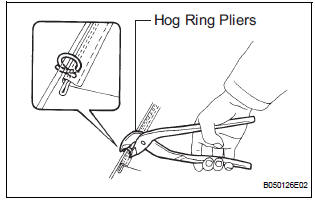
- Using hog ring pliers, completely install the seatback cover with new hog rings.
NOTICE:
- Be careful not to damage the cover.
- When installing the hog rings, take care to prevent wrinkles as much as possible.
9. INSTALL SEATBACK COVER WITH PAD
- Install the seatback cover with pad.

- Using hog ring pliers, install new hog rings and hooks.
NOTICE:
- Be careful not to damage the cover.
- When installing the hog rings, take care to minimize wrinkles as much as possible.
- with Side airbag:
Install the seatback cover bracket with the nut.
Torque: 5.5 N*m (56 kgf*cm, 48 in.*lbf)
NOTICE:
- For a vehicle with side airbag, the side airbag may not be activated normally unless the seatback cover is securely installed.
- Check that the strap has no twist after installing the bracket.
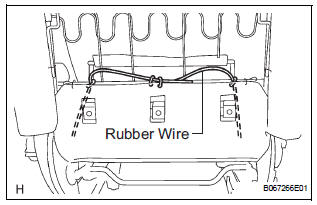
- Engage the rubber wire with a hole of the front seatback frame with new hog rings, as shown in the illustration.
- Using hog ring pliers, install new hog rings.
NOTICE:
- Be careful not to damage the cover.
- When installing the hog rings, take care to prevent wrinkles as much as possible.
10. INSTALL FRONT SEAT HEADREST SUPPORT
- Install the 2 headrest supports.
11. INSTALL LUMBAR SUPPORT KNOB LH (for Driver Seat)
- Install the lumbar support knob with the snap ring.
12. INSTALL FRONT SEATBACK BOARD LH
- Install the seatback board LH.
13. INSTALL SEAT CUSHION COVER WITH PAD
- Install the seat cushion cover with pad.
- Install the clamps and hooks.
14. INSTALL FRONT SEAT INNER LH ARMREST ASSEMBLY
- Install the armrest with the bolt.
Torque: 20 N*m (200 kgf*cm, 14 ft.*lbf)
- Install the seat armrest cap.
15. INSTALL SEPARATE TYPE FRONT SEAT CUSHION COVER

- Install the seat cushion pad to the seat cushion cover.
- Using hog ring pliers, install the seat cushion cover to the seat cushion pad with new hog rings.
NOTICE:
- Be careful not to damage the cover.
- When installing the hog rings, take care to prevent wrinkles as much as possible.
16. INSTALL FRONT SEAT TRACK COVER LH FRONT INNER
- Install the seat track cover LH front inner with the clip and 2 screws.
17. INSTALL FRONT SEAT TRACK COVER LH FRONT OUTER
- Install the seat track cover LH front outer with the clip and 2 screws.
18. INSTALL FRONT SEAT CUSHION SHIELD INNER LH
- Install the cushion shield.
- Install the screw.
19. INSTALL FRONT SEAT INNER BELT ASSEMBLY LH
- Install the inner belt assembly with the nut.
Torque: 41 N*m (418 kgf*cm, 30 ft.*lbf) HINT: Check that the inner seat belt assembly moves smoothly.
- Connect the connectors.
20. INSTALL FRONT SEAT CUSHION SHIELD LH
- Install the front seat cushion shield LH.
- Install the screw.
21. INSTALL RECLINING ADJUSTER RELEASE HANDLE LH
- Install the reclining adjuster release handle LH.
22. INSTALL VERTICAL SEAT ADJUSTER KNOB (for Driver Seat)
- Install the vertical seat adjuster knob with the screw.
- Install the vertical seat adjuster knob cover.
23. INSTALL OCCUPANT CLASSIFICATION ECU (for Front Passenger Seat)
24. INSTALL FRONT SEAT SIDE TABLE (w/ Table)
- Install the seat side table with 4 nuts.
Torque: 13 N*m (133 kgf*cm, 10 ft.*lbf)
25. INSTALL FRONT SEAT SIDE TABLE LEG COVER (w/ Table)
- Install the front seat side table leg cover.
 Disassembly
1. REMOVE FRONT SEAT SIDE TABLE LEG COVER (w/
Table)
Using a screwdriver, disengage the claws and
remove the seat side table leg cover.
HINT:
Tape the screwdriver tip before use.
2. ...
 Installation
1. INSTALL FRONT SEAT ASSEMBLY LH
Place the seat assembly in the cabin.
NOTICE:
Be careful not to damage the body.
Connect the connectors under the seat assembly.
T ...
Other materials:
Rear Airbag Sensor LH Circuit Malfunction
DTC B1155/39 Rear Airbag Sensor LH Circuit Malfunction
DESCRIPTION
The rear airbag sensor LH circuit consists of the center airbag sensor
assembly and rear airbag sensor
LH.
If the center airbag sensor assembly receives signals from the rear airbag
sensor LH, it judges whether or
not the ...
Active Control Engine Mount System
DESCRIPTION
LOCATION
The Active Control Engine Mount (ACM) system decreases engine vibration at
engine idling using the
ACM VSV. The VSV is controlled by a pulse signal transmitted to the VSV from the
ECM. The frequency
of this pulse signal is matched to the engine speed to decrease engine ...
For manual air conditioning system
ON-VEHICLE INSPECTION
1. INSPECT AIR INLET CONTROL SERVO MOTOR
(a) Remove the air inlet control servo motor.
(b) Connect the positive (+) lead from the battery to
terminal 5 and negative (-) lead to terminal 1, then
check that the lever turns to "RECIRCULATION"
side smoothly.
...
