Toyota Sienna Service Manual: Reassembly
1. INSTALL SEAT POSITION AIRBAG SENSOR (for Driver Seat)
2. INSTALL LUMBAR SUPPORT ADJUSTER ASSEMBLY LH
- Install the seat side table leg cover.
3. INSTALL FRONT SEAT CUSHION SHIELD LOWER LH
- Install the front seat cushion shield lower LH with the screw.
4. INSTALL FRONT SEAT CUSHION SHIELD LOWER RH
HINT: Use the same procedures for the RH side and LH side.
5. INSTALL RECLINING ADJUSTER INSIDE COVER LH
- Install the reclining adjuster inside cover LH (upper) with the screw.
6. INSTALL RECLINING ADJUSTER INSIDE COVER RH
HINT: Use the same procedures for the RH side and LH side.
7. INSTALL RECLINING ADJUSTER INSIDE COVER RH
- Install the reclining adjuster inside cover RH (lower) with the 2 screws.
- Install the clamp.
8. INSTALL RECLINING ADJUSTER INSIDE COVER LH
- Install the reclining adjuster inside cover LH (lower) with the 2 screws.
9. INSTALL FRONT SEATBACK HEATER ASSEMBLY LH (w/ Seat Heater System)
- Place the seat heater on the seatback cover.
- Install the seat heater to the seatback cover with new tack pins.
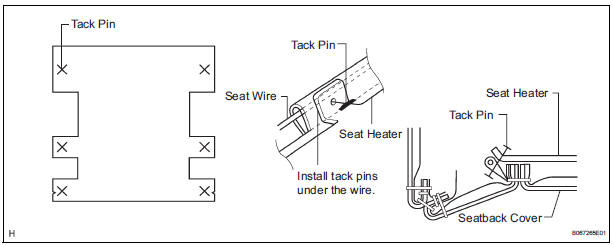
NOTICE: Do not substitute other metal parts for tack pins.
10. INSTALL FRONT SEATBACK COVER LH
- Install the seatback pad.
- Cover the top of the seatback pad with the seatback cover.
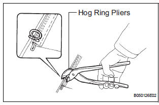
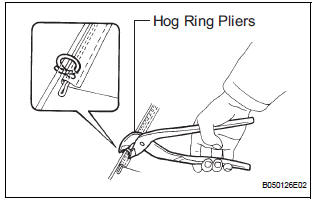
- Using hog ring pliers, completely install the seatback cover with new hog rings.
NOTICE:
- Be careful not to damage the cover.
- When installing the hog rings, take care to prevent wrinkles as much as possible.
11. INSTALL SEATBACK COVER WITH PAD
- Install the seatback cover with pad.
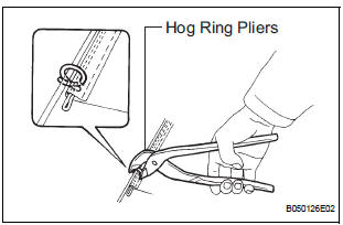
- Using hog ring pliers, install new hog rings and hooks.
NOTICE:
- Be careful not to damage the cover.
- When installing the hog rings, take care to minimize wrinkles as much as possible.
- with Side airbag:
Install the seatback cover bracket with the nut.
Torque: 5.5 N*m (56 kgf*cm, 48 in.*lbf)
NOTICE:
- For a vehicle with side airbag, the side airbag may not be activated normally unless the seatback cover is securely installed.
- Check that the strap has no twist after installing the bracket.
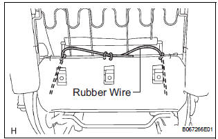
- Attach a rubber wire with new hog rings, as shown in the illustration.
- Using hog ring pliers, install new hog rings.
NOTICE:
- Be careful not to damage the cover.
- When installing the hog rings, take care to prevent wrinkles as much as possible.
12. INSTALL FRONT SEAT HEADREST SUPPORT
- Install the 2 headrest supports.
13. INSTALL FRONT SEATBACK BOARD LH
- Install the front seatback board LH.
14. INSTALL FRONT SEAT INNER LH ARMREST ASSEMBLY
- Install the armrest with the bolt.
Torque: 20 N*m (200 kgf*cm, 14 ft.*lbf)
- Install the armrest cap.
15. INSTALL FRONT SEAT CUSHION HEATER ASSEMBLY LH (w/ Seat Heater System)
- Place the seat heater on the seat cushion cover.
- Install the seat heater to the seat cushion cover with new tack pins.
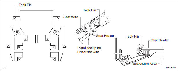
NOTICE: Do not substitute other metal parts for tack pins.
16. INSTALL SEPARATE TYPE FRONT SEAT CUSHION COVER
- Install the seat cushion pad to the seat cushion cover.
- Using hog ring pliers, install the seat cushion cover to the seat cushion pad with new hog rings.
NOTICE:
- Be careful not to damage the cover.
- When installing the hog rings, take care to prevent wrinkles as much as possible.
17. INSTALL SEAT CUSHION COVER WITH PAD
- Install the seat cushion cover with pad.
- Install the clamps and hooks.
- with Seat heater: Connect the connector.
18. INSTALL FRONT SEAT TRACK COVER LH FRONT INNER
- Install the seat track cover front inner with the clip and 2 screws.
19. INSTALL FRONT SEAT TRACK COVER LH FRONT OUTER
- Install the seat track cover front outer with the clip and 2 screws.
20. INSTALL FRONT SEAT INNER BELT ASSEMBLY LH
- Install the inner belt assembly with the nut.
Torque: 41 N*m (418 kgf*cm, 30 ft.*lbf) HINT: Check that the inner seat belt assembly moves smoothly.
- Connect the connectors.
21. INSTALL FRONT POWER SEAT SWITCH LH
- Install the power seat switch LH with the 3 screws.
- Connect the connector.
22. INSTALL POWER SEAT SWITCH (for Driver Seat)
- Install the power seat switch with the 2 screws.
23. INSTALL NO. 1 FRONT SEAT CUSHION SHIELD INNER LH
- Install the No. 1 front seat cushion shield inner LH to the front seat cushion shield LH with the screw.
24. INSTALL FRONT SEAT CUSHION SHIELD INNER LH
- Install the front seat cushion shield inner LH to the No. 1 front seat cushion shield inner LH with the screw.
- Install the front seat cushion shield LH together with front seat cushion shield inner LH and No. 1 front seat cushion shield inner LH.
- Install the 7 screws.
25. INSTALL SLIDE & VERTICAL POWER SEAT SWITCH KNOB
- Install the reclining power seat switch knob.
26. INSTALL RECLINING POWER SEAT SWITCH KNOB
- Install the reclining power seat switch knob.
27. INSTALL OCCUPANT CLASSIFICATION ECU (for Front Passenger Seat)
28. INSTALL FRONT SEAT SIDE TABLE (w/ Table)
- Install the seat side table with 4 nuts.
Torque: 13 N*m (133 kgf*cm, 10 ft.*lbf)
29. INSTALL FRONT SEAT SIDE TABLE LEG COVER (w/ Table)
- Install the seat side table leg cover.
 Disassembly
1. REMOVE FRONT SEAT SIDE TABLE LEG COVER (w/
Table)
Using a screwdriver, disengage the claws and
remove the seat side table leg cover.
HINT:
Tape the screwdriver tip before use.
2. ...
 Installation
1. INSTALL FRONT SEAT ASSEMBLY LH
Place the seat assembly in the cabin.
NOTICE:
Be careful not to damage the body.
Connect the connectors under the seat assembly.
T ...
Other materials:
Installation
1. INSTALL CENTER AIRBAG SENSOR ASSEMBLY
Check that the ignition switch is off.
Check that the battery negative (-) terminal is
disconnected.
CAUTION:
After disconnecting the negative battery
terminal, wait for at least 90 seconds before
starting the operation.
Temporar ...
Oxygen Sensor Heater Control Circuit
HINT:
Sensor 2 refers to the sensor mounted behind the Three-Way Catalytic
Converter (TWC) and located
furthest from the engine assembly.
DESCRIPTION
Refer to DTC P0136 (See page ES-160).
HINT:
When any of these DTCs are set, the ECM enters fail-safe mode. The ECM turns
off the Heated ...
Installation
1. INSTALL FRONT SHOULDER BELT ANCHOR
ADJUSTER ASSEMBLY
Install the front shoulder belt anchor adjuster
assembly with the bolt.
Torque: 42 N*m (430 kgf*cm, 31 ft.*lbf)
2. INSTALL CENTER PILLAR UPPER GARNISH
3. INSTALL FRONT SEAT OUTER BELT ASSEMBLY
NOTICE:
Do not disassemble ...
