Toyota Sienna Service Manual: Low Battery Positive Voltage
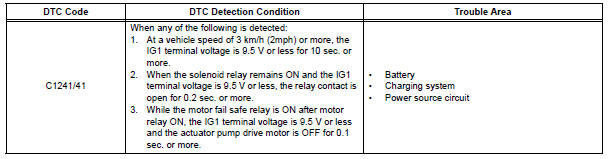
DTC C1241/41 Low Battery Positive Voltage
DESCRIPTION
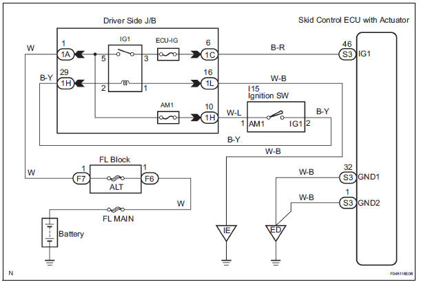
WIRING DIAGRAM
INSPECTION PROCEDURE
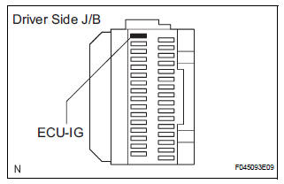
1 INSPECT ECU-IG FUSE
(a) Remove the ECU-IG fuse from the driver side J/B.
(b) Check continuity of the ECU-IG fuse.
Standard resistance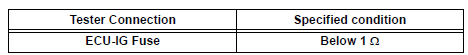


2 CHECK BATTERY
(a) Check the positive battery voltage.
Standard voltage: 11 to 14 V

3 INSPECT SKID CONTROL ECU (IG1 TERMINAL)
(a) WHEN USING INTELLIGENT TESTER: (1) Connect the intelligent tester to the DLC3.
(2) Start the engine.
(3) Select the DATA LIST mode on the intelligent tester.
ABS / VSC:
(4) Check that the voltage condition output from the ECU displayed on the intelligent tester.
OK: "Normal" is displayed.
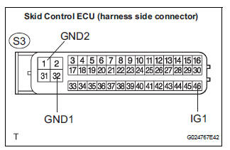
(b) WHEN NOT USING INTELLIGENT TESTER: (1) Disconnect the skid control ECU connector.
(2) Turn the ignition switch to the ON position.
(3) Measure the voltage according to the value(s) in the table below.
Standard voltage 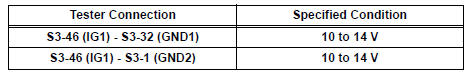
NOTICE: When replacing the brake actuator assembly, perform zero point calibration (See page BC-70).

REPLACE BRAKE ACTUATOR ASSEMBLY
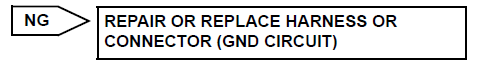
4 INSPECT SKID CONTROL ECU (GND TERMINAL)
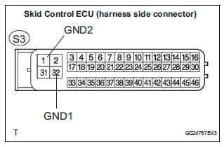
(a) Disconnect the skid control ECU connector.
(b) Measure the resistance according to the value(s) in the table below.
Standard resistance 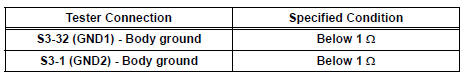

REPAIR OR REPLACE HARNESS OR CONNECTOR (IG1 CIRCUIT)
 Stuck in Deceleration Sensor
DESCRIPTION
The yaw rate sensor and deceleration sensor signal is sent to the skid
control ECU through the CAN
communication system. When there is a malfunction in the communication, it will
...
 Master Cylinder Pressure Sensor Malfunction
DTC C1246/46 Master Cylinder Pressure Sensor Malfunction
DESCRIPTION
Master cylinder pressure sensor is connected to the skid control ECU in the
actuator.
INSPECTION PROCEDURE
1 READ VALUE O ...
Other materials:
Identification of noise source
1. Radio Description
Radio frequency band
Radio broadcasts use the radio frequency bands
shown in the table below
Service area
The service areas of AM and FM broadcasts are
vastly different. Sometimes an AM broadcast
can be received very clearly but an FM st ...
Short to GND in Curtain Shield Squib RH Circuit
DTC B1162/81 Short to GND in Curtain Shield Squib RH Circuit
DESCRIPTION
The curtain shield squib RH circuit consists of the center airbag sensor
assembly and the curtain shield
airbag assembly RH.
The circuit instructs the SRS to deploy when deployment conditions are met.
DTC B1162/81 is ...
Diagnosis system
1. CHECK DLC3
The ECU uses ISO 15765-4 for communication.
The terminal arrangement of the DLC3 complies
with SAE J1962 and meets the ISO 15765-4 format.
NOTICE:
*: Before measuring the resistance, leave the
vehicle as is for at least 1 minute and do not
operate the ignition s ...
