Toyota Sienna Service Manual: Reassembly
1. INSTALL FRONT OIL PUMP OIL SEAL

(a) Using SST and a hammer, install a new oil seal to the oil pump body.
SST 09350-32014 (09351-32140)
HINT:
The seal end should be flat with the outer edge of the oil pump.
(b) Coat the lip of the oil seal with MP grease.
2. INSTALL FRONT OIL PUMP BODY O-RING
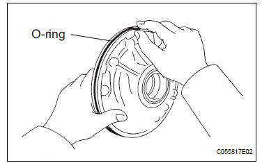
(a) Coat new O-ring with ATF, and install it to the oil pump body.
NOTICE:
Make sure that the O-ring is not twisted or pinched. Moreover, apply enough ATF to the Oring before installation.
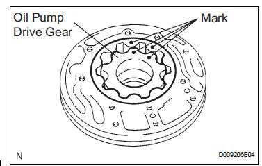
3. INSTALL FRONT OIL PUMP DRIVEN GEAR
(a) Coat the front oil pump driven gear with ATF, and install it to the oil pump body with the marked side facing upward.
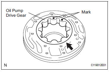
4. INSTALL FRONT OIL PUMP DRIVE GEAR
(a) Coat the front oil pump drive gear with ATF, and install it to the oil pump body with the marked side facing upward.
5. INSTALL STATOR SHAFT ASSEMBLY
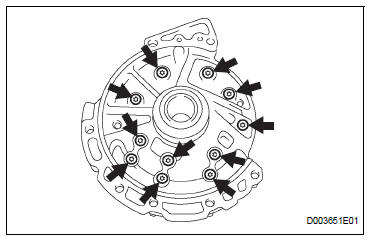
a) Set the stator shaft and align it with each bolt hole.
(b) Using a "torx" socket (T30), install the 11 bolts.
Torque: 9.8 N*m (100 kgf*cm, 87 in.*lbf)
6. INSTALL CLUTCH DRUM OIL SEAL RING
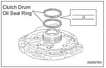
(a) Coat 2 new clutch drum oil seal rings with ATF.
(b) Install 2 new clutch drum oil seal rings.
NOTICE: Do not expand the ring ends excessively.
7. INSPECT OIL PUMP ASSEMBLY
HINT: (See page AX-234)
 Inspection
1. INSPECT OIL PUMP ASSEMBLY
(a) Turn the drive gear with the 2 screwdrivers and
make sure that it rotates smoothly.
NOTICE:
Be careful not to damage the oil seal lip.
2. INSPEC ...
 Second brake piston
COMPONENTS
...
Other materials:
Clock setting
Display the “General Settings” screen.
Operations up to this point can also be performed by select the clock
display
at the top of most screens.
Select the items to be set.
Manual clock setting
Set minutes to 00
The 24-hour time format can
be to on/off.
Select â ...
Disassembly
1. REMOVE FRONT SEAT SIDE TABLE LEG COVER (w/
Table)
Using a screwdriver, disengage the claws and
remove the seat side table leg cover.
HINT:
Tape the screwdriver tip before use.
2. REMOVE FRONT SEAT SIDE TABLE (w/ Table)
Remove the 4 nuts and seat side table.
Rem ...
Camshaft Position "B" Actuator Circuit / Open
DTC P0013 Camshaft Position "B" Actuator Circuit / Open
(Bank 1)
DTC P0023 Camshaft Position "B" Actuator Circuit / Open
(Bank 2)
DESCRIPTION
The Variable Valve Timing (VVT) system includes the ECM, OCV and VVT
controller. The ECM sends a
target duty-cycle control signal ...
