Toyota Sienna Service Manual: Touch Panel Switch does not Function
INSPECTION PROCEDURE
1 CHECK TOUCH PANEL
- Check for foreign matter on the display.
OK: The display is clean
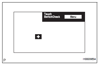
2 CHECK TOUCH SWITCH (DISPLAY CHECK MODE)

- Enter the "Display Check" mode (Touch Switch Check).
- Touch the display in the area where the switch malfunction occurs.
OK: A "+" mark appears at the touched position.
REPLACE RADIO AND NAVIGATION ASSEMBLY
 Panel Switches do not Function
INSPECTION PROCEDURE
1 CHECK PANEL SWITCH
Check for foreign matter around the switches that might
prevent operation.
OK:
No foreign matter is found
2 CHECK PANEL SWITCH (DISPLAY CHECK MODE ...
 Display Panel does not Open, Tilt or Tilts Improperly
INSPECTION PROCEDURE
1 CHECK RADIO AND NAVIGATION ASSEMBLY
Check for foreign matter or obstructions caught in the
moving parts of the panel.
OK:
No obstruction or foreign matter found.
...
Other materials:
Fastening the seat belt (for the third center seat)
Take the plate out of the holder,
and then pull down the seat
belt.
Push plate “A” into buckle “A”
until a click sound is heard.
Push plate “B” into buckle “B”
until a click sound is heard.
...
Reassembly
1. INSTALL BRAKE PEDAL PAD
(a) Install the brake pedal pad to the brake pedal subassembly.
2. INSTALL PUSH ROD PIN
(a) Apply lithium soap base glycol grease to inside
surface of 2 new push rod bushes.
(b) Install the 2 new push rod bushes.
(c) Install the 2 push rod pins with the 2 plate t ...
Automatic door locking and unlocking systems
The following functions can be set or cancelled: For instructions on
customizing, refer to
Function
Operation
Shift position linked door
locking function
Shifting the shift lever out of P locks all the
doors
Shift position linked door
unlocking function
...
