Toyota Sienna Service Manual: Removal
HINT: Remove the RH side by the same procedure as the LH side.
1. REMOVE FRONT WHEEL
2. DRAIN BRAKE FLUID
NOTICE: Wash the brake fluid off immediately if it attaches to any painted surface.
3. REMOVE FRONT DISC BRAKE CYLINDER SUBASSEMBLY
(a) Remove the union bolt and 2 gaskets from the front disc brake cylinder sub-assembly, then disconnect the flexible hose.
(b) Hold the front disc brake cylinder slide pin and remove the 2 bolts.
4. REMOVE DISC BRAKE PAD KIT FRONT (PAD ONLY)
(a) Remove the disc brake pad kit front from the front disc brake cylinder mounting LH.
5. REMOVE ANTI SQUEAL SHIM KIT FRONT
(a) Remove the anti squeal shim and pad wear indicator plate from the each pad.
6. REMOVE FRONT DISC BRAKE PAD SUPPORT PLATE
(a) Remove the front disc brake pad support plate (No.
1) and front disc brake pad support plate (No. 2) from the front disc brake cylinder mounting LH.
7. REMOVE FRONT DISC BRAKE CYLINDER SLIDE PIN
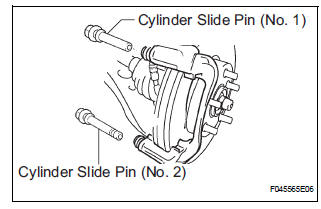
(a) Remove the front disc brake cylinder slide pin (No.
1) and front disc brake cylinder slide pin (No. 2) from the front disc brake cylinder mounting LH.
8. REMOVE FRONT DISC BRAKE CYLINDER SLIDE BUSH
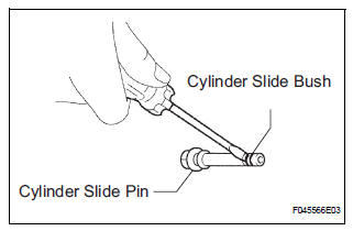
(a) Using a screwdriver, remove the front disc brake cylinder slide bush from the front disc brake cylinder slide pin (No. 2).
NOTICE: Do not damage the front disc brake cylinder slide pin (No. 2).
9. REMOVE FRONT DISC BRAKE CYLINDER MOUNTING LH
(a) Remove the 2 bolts and front disc brake cylinder mounting LH.
 Front brake
COMPONENTS
...
 Disassembly
1. REMOVE FRONT DISC BRAKE BUSH DUST BOOT
(a) Using soft jaws on the vise, hold the front disc brake
cylinder mounting LH in the vise through aluminum
plates.
(b) Using a screwdriver and ham ...
Other materials:
Diagnostic trouble code chart
HINT:
The parameters listed in the chart may not confirm exactly to
those read during the DTC check due to the type of
instrument or other factors.
If a trouble code is displayed during the DTC check in the
check mode, check the circuit for the code listed in the table
below. For details of ...
A/C ECU Communication Stop
DTC B1262 A/C ECU Communication Stop
DESCRIPTION
DTC B1262 is output when communication between the A/C amplifier and the
multiplex network gateway
ECU stops for more than 10 seconds.
DTC No.
DTC Detection Condition
Trouble Area
B1262
A/C ECU communicat ...
Dtc check / clear
1. DTC CHECK (NORMAL MODE)
NOTICE:
When the diagnostic system is switched from the
normal mode to the check mode, all the DTCs and
freeze frame data recorded in the normal mode will
be erased. So before switching modes, always check
the DTCs and freeze frame data, and note the ...
