Toyota Sienna Service Manual: Disassembly
1. REMOVE FRONT DISC BRAKE BUSH DUST BOOT
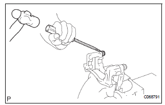
(a) Using soft jaws on the vise, hold the front disc brake cylinder mounting LH in the vise through aluminum plates.
(b) Using a screwdriver and hammer, remove the 2 front disc brake bush dust boots from the front disc brake cylinder mounting LH.
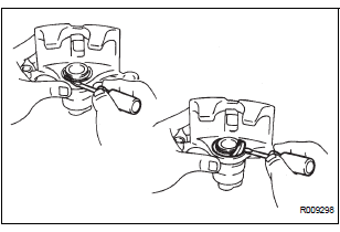
2. REMOVE CYLINDER BOOT
(a) Using a screwdriver, remove the set ring and cylinder boot.
3. REMOVE FRONT DISC BRAKE PISTON
(a) Place a shop rug, between the front disc brake piston and the disc brake cylinder sub-assembly.
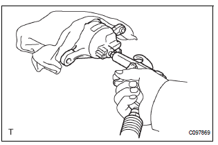
(b) Use compressed air to remove the front disc brake piston from the disc brake cylinder sub-assembly.
| CAUTION: Do not place your fingers in front of the piston when using compressed air. |
NOTICE: Do not spatter the brake fluid.
4. REMOVE PISTON SEAL
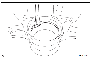
(a) Using a screwdriver, remove the piston seal from the front disc brake cylinder sub-assembly.
NOTICE: Do not damage the inner cylinder and cylinder groove.
5. REMOVE FRONT DISC BRAKE BLEEDER PLUG
(a) Remove the front disc brake bleeder plug from the front disc brake cylinder sub-assembly.
6. REMOVE FRONT DISC BRAKE BLEEDER PLUG CAP
7. REMOVE FRONT DISC
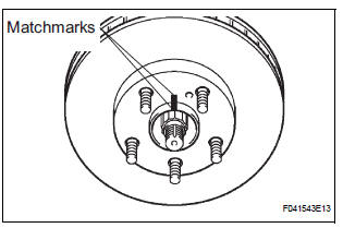
(a) Place matchmarks on the front disc and the axle hub.
(b) Remove the front disc.
 Removal
HINT:
Remove the RH side by the same procedure as the LH side.
1. REMOVE FRONT WHEEL
2. DRAIN BRAKE FLUID
NOTICE:
Wash the brake fluid off immediately if it attaches to
any painted surface.
3. ...
 Inspection
1. INSPECT BRAKE CYLINDER AND PISTON
(a) Check the brake cylinder bore and front disc brake
piston for rust or scoring.
2. INSPECT PAD LINING THICKNESS
(a) Using a ruler, measure the pad linin ...
Other materials:
Throttle / Pedal Position Sensor/ Switch
DTC P2120 Throttle / Pedal Position Sensor / Switch "D"
Circuit
DTC P2122 Throttle / Pedal Position Sensor / Switch "D"
Circuit Low Input
DTC P2123 Throttle / Pedal Position Sensor / Switch "D"
Circuit High Input
DTC P2125 Throttle / Pedal Position Sensor / Switch ...
Master Reset/ Voice Processing Device ON Error
DTC 01-DD Master Reset
DTC 01-E1 Voice Processing Device ON Error
DESCRIPTION
HINT:
*1: This code may be stored if the engine is started and the ignition switch is
turned to START position
again.
*2: Even if no fault is present, this trouble code may be stored depending on
the battery ...
Removal
1. RECOVER REFRIGERANT FROM REFRIGERATION
SYSTEM (See page AC-172)
2. REMOVE FRONT WHEEL RH
3. REMOVE FRONT FENDER APRON SEAL RH (See
page EM-26)
4. REMOVE V-RIBBED BELT (See page EM-6)
5. REMOVE RADIATOR AND FAN ASSEMBLY
(See page CO-28)
6. DISCONNECT DISCHARGE HOSE SUB-ASSEMBLY
(a) Re ...
