Toyota Sienna Service Manual: Indicator Circuit
DESCRIPTION
The indicator displays the location of the obstacle and the approximate distance between the vehicle and the obstacle either by blinking or turning on.
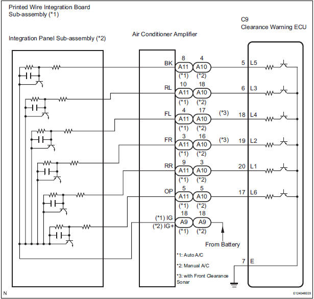
WIRING DIAGRAM
INSPECTION PROCEDURE
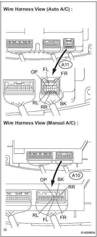
1 CHECK HARNESS AND CONNECTOR (CLEARANCE WARNING ECU - AIR CONDITIONER AMPLIFIER)
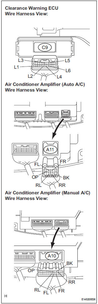
- Disconnect the connectors from the clearance warning ECU C9 and air conditioner amplifier connector A10 or A11.
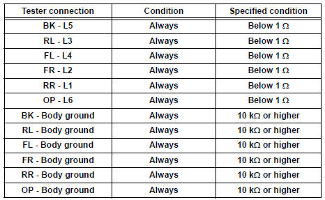
- Measure the resistance according to the value(s) in the table below.
Standard resistance
2 INSPECT INDICATOR
- Remove the integration control & panel assembly with the connectors being connected.
- Using a service wire, ground each terminal of the integration control & panel assembly connector.
- Turn the ignition switch ON.
- Check that each LED comes on.
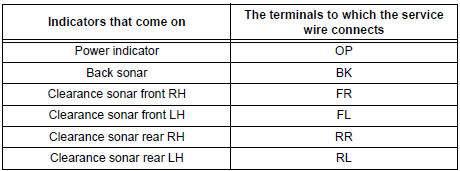
Result
PROCEED TO NEXT CIRCUIT INSPECTION SHOWN IN PROBLEM SYMPTOMS TABLE
3 INSPECT PRINTED WIRE INTEGRATION BOARD SUB-ASSEMBLY
- Check the malfunction disappears when a known good printed wire integration board sub-assembly is installed
OK: Malfunction disappears.
REPLACE PRINTED WIRE INTEGRATION BOARD SUB-ASSEMBLY
4 INSPECT INTEGRATION PANEL SUB-ASSEMBLY
- Check that the malfunction disappears when a known good integration panel sub-assembly is installed.
OK: Malfunction disappears
REPLACE INTEGRATION PANEL SUB-ASSEMBLY
 No. 2 Clearance Warning Buzzer Circuit
DESCRIPTION
The clearance warning ECU receives the ultrasonic sensor signal to sound the
rear warning buzzer.
WIRING DIAGRAM
INSPECTION PROCEDURE
1 CHECK HARNESS AND CONNECTOR (CLEARANCE WAR ...
 Horn
Horn
...
Other materials:
Suspension
SST
RECOMMENDED TOOLS
EQUIPMENT
TIRE AND WHEEL
RECOMMENDED TOOLS
EQUIPMENT
...
Removal
1. REMOVE REAR DOOR SCUFF PLATE LH
2. REMOVE REAR DOOR WEATHERSTRIP LH
3. REMOVE BACK DOOR WEATHERSTRIP
4. REMOVE BACK DOOR SCUFF PLATE
5. REMOVE QUARTER TRIM FRONT PANEL ASSEMBLY LH
6. REMOVE POWER POINT SOCKET ASSEMBLY
Release the 2 claw fittings and remove the power
point soc ...
Removal
1. REMOVE WINDSHIELD WIPER MOTOR ASSEMBLY
2. REMOVE FRONT OUTER COWL TOP PANEL SUBASSEMBLY
3. DRAIN ENGINE COOLANT
4. REMOVE V-BANK COVER SUB-ASSEMBLY
5. REMOVE NO. 2 AIR CLEANER INLET
6. REMOVE NO. 1 AIR CLEANER INLET
7. REMOVE AIR CLEANER CAP SUB-ASSEMBLY
Disconnect the 3 vacuum hoses.
...
