Toyota Sienna Service Manual: Removal
1. REMOVE INSTRUMENT PANEL SUB-ASSEMBLY WITH PASSENGER AIRBAG ASSEMBLY
HINT: Refer to the instructions for removal of the instrument panel sub-assembly w/ passenger airbag assembly (See page IP-5).
2. REMOVE HEATER TO FOOT DUCT NO.1
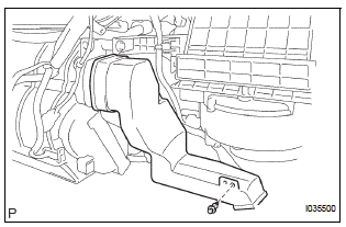
(a) Remove the clip and the heater to foot duct No. 1.
3. REMOVE STEREO COMPONENT AMPLIFIER ASSEMBLY (w/ Stereo Compartment Amplifier) (See page AV-173)
4. REMOVE ECM (See page ES-498)
5. REMOVE BLOWER ASSEMBLY
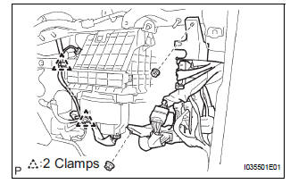
(a) Release the 2 clamps, the 2 nuts and the wire harness.
(b) Remove the bolt, the 2 screws and the nut.
(c) Remove the blower assembly.
 Blower unit
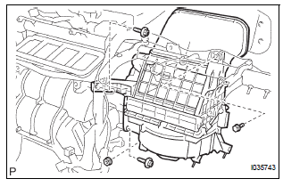
COMPONENTS
...
 Disassembly
1. REMOVE AIR REFINER ELEMENT
(a) Release the 2 claw fittings and remove the air filter
sub-assembly.
(b) Remove the air refiner element from the air filter
cover plate.
2. REMOVE COOLING ...
Other materials:
Check for intermittent
problems
1. CHECK FOR INTERMITTENT PROBLEMS
HINT:
For use of the intelligent tester only:
Inspect the vehicle's ECM using check mode.
Intermittent problems are easier to detect with an
intelligent tester when the ECM is in check mode. In
check mode, the ECM uses 1 trip detection logic, which
is more ...
Short in Driver Side Squib 2nd Step Circuit
DTC B1180/17 Short in Driver Side Squib 2nd Step Circuit
DESCRIPTION
The driver side squib 2nd step circuit consists of the center airbag sensor
assembly, the spiral cable and
the steering pad.
The circuit instructs the SRS to deploy when deployment conditions are met.
DTC B1180/17 is rec ...
Crankshaft position sensor
Components
Removal
1. Remove compressor and magnetic clutch
HINT:
(See page AC-227 )
2. REMOVE CRANKSHAFT POSITION SENSOR
(a) Disconnect the crankshaft position sensor
connector.
(b) Remove the bolt, and then remove the crankshaft
position sensor.
INSPECTION
1. INSPECT CRANKSHAFT ...
