Toyota Sienna Service Manual: Brake Warning Light does not Come ON
WIRING DIAGRAM
See page BC-52.
INSPECTION PROCEDURE
1 INSPECT BRAKE WARNING LIGHT
(a) Disconnect the skid control ECU connector.
(b) Turn the ignition switch to the on position.
(c) Check that the BRAKE warning light comes on.
OK: BRAKE warning light comes on.
HINT: If troubleshooting has been carried out according to the PROBLEM SYMPTOMS TABLE, refer back to the table and proceed to the next step before replacing the part (See page BC-7).

REPLACE BRAKE ACTUATOR ASSEMBLY
2 CHECK HARNESS AND CONNECTOR (BETWEEN SKID CONTROL ECU AND COMBINATION METER ASSEMBLY)
(a) Turn the ignition switch off.
(b) Disconnect the combination meter connector.
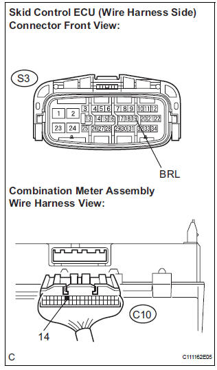
(c) Measure the resistance according to the value(s) in the table below.
Standard resistance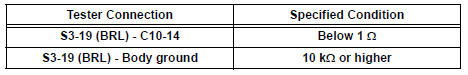

3 INSPECT COMBINATION METER ASSEMBLY
(a) Check the combination meter assembly (See page ME- 4).
HINT: If troubleshooting has been carried out according to the PROBLEM SYMPTOMS TABLE, refer back to the table and proceed to the next step before replacing the part (See page BC-7).

END
 Brake Warning Light Remains ON
DESCRIPTION
If the ECU detects a trouble, it turns on the brake warning light at the same
time of prohibiting ABS
control.
At this time, the ECU records a DTC in memory.
Connect terminals TC ...
 TC and CG Terminal Circuit
DESCRIPTION
DTC output mode is set by connecting terminals TC and CG of the DLC3.
The DTCs are displayed by the blinking pattern of the ABS warning light.
WIRING DIAGRAM
HINT:
When warning ...
Other materials:
Operating Light Control Rheostat does not Change Light Brightness
DESCRIPTION
The meter CPU receives signals for adjusting illumination on the meter from
this circuit. The meter CPU
detects the illumination level selected by the user according to the position of
the rheostat knob.
WIRING DIAGRAM
INSPECTION PROCEDURE
1 READ VALUE OF INTELLIGENT TESTER ...
Registering and connecting from the “Bluetooth* Setup” screen
To display the screen shown below, press the “SETUP” button and
select “Bluetooth*” on the “Setup” screen.
Select to connect the device to
be used with audio system.
Select to register a Bluetooth® device to be used with audio system.
Select to set detailed
Blueto ...
Power window regulator
motor
INSPECTION
1. INSPECT POWER WINDOW REGULATOR MOTOR
(FRONT RH)
Remove the power window regulator motor.
Apply battery voltage to the motor connector
according to the table below.
NOTICE:
Do not apply battery to any terminals except
terminals 1 and 2.
Standard
2. INS ...
