Toyota Sienna Service Manual: Removal
1. REMOVE INSTRUMENT CLUSTER NO.1 FINISH PANEL CENTER
2. REMOVE INSTRUMENT CLUSTER NO.2 FINISH PANEL CENTER
3. REMOVE INSTRUMENT CLUSTER FINISH PANEL GARNISH
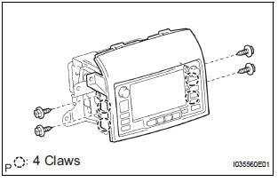
4. REMOVE NAVIGATION RECEIVER ASSEMBLY WITH BRACKET
- Remove the 4 screws.
- Disconnect the connector and remove the navigation receiver assembly with bracket.
5. REMOVE INSTRUMENT CLUSTER FINISH PANEL UPPER
- Remove the 4 screws and the instrument cluster finish panel upper.
6. REMOVE NO.1 NAVIGATION BRACKET
- Remove the 4 screws and the No.1 navigation bracket.
7. REMOVE NO.2 NAVIGATION BRACKET
- Remove the 4 screws and the No.2 navigation bracket from the navigation receiver assembly.
 Navigation receiver
COMPONENTS
...
 Installation
1. INSTALL NO.1 NAVIGATION BRACKET
Install the No.1 navigation bracket with the 4
screws.
2. INSTALL NO.2 NAVIGATION BRACKET
Install the No.2 navigation bracket with t ...
Other materials:
Player Error
DTC 58-44 Player Error
DTC 80-44 Player Error
DESCRIPTION
DTC No.
DTC Detection Condition
Trouble Area
58-44
Map player error is detected
Radio and navigation assembly
80-44
Map player error is detected.
INSPECTION PROCEDURE
HINT: ...
How to proceed with
troubleshooting
HINT:
Use this procedure to troubleshoot the theft deterrent
system.
The intelligent tester should be used in step 2.
1 VEHICLE BROUGHT TO WORKSHOP
2 CUSTOMER PROBLEM ANALYSIS
Interview the customer to confirm the trouble
3 INSPECT COMMUNICATION FUNCTION OF MULTIPLEX COMMUNI ...
Compressor Lock Sensor Circuit
DTC B1422/22 Compressor Lock Sensor Circuit
SYSTEM DESCRIPTION
The ECM sends an engine speed signal to the A/C amplifier via CAN
communication and BEAN
communication.
The A/C amplifier reads the difference between compressor speed and engine
speed. When the
difference becomes too large, t ...
