Toyota Sienna Service Manual: Reassembly
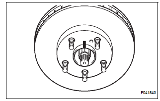
1. INSTALL REAR DISC

(a) Aligning the matchmarks, install the rear disc.
HINT: Select the installation position where the disc has the minimum runout.
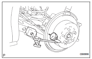
2. INSPECT DISC RUNOUT
(a) Temporarily fasten the disc with the hub nuts.
Torque: 103 N*m (1,050 kgf*cm, 76 ft.*lbf)

(b) Using a dial indicator, measure the disc runout 10 mm (0.39 in.) away from the outer edge of the disc.
Maximum disc runout: 0.10 mm (0.0039 in.) (c) If the disc runout is the maximum value or greater, check the bearing play in the axial direction and check for the axle hub runout (See page AH-16). If the bearing play and axle hub runout are normal, adjust the disc runout or grind it on a "On-car" brake lathe.
3. ADJUST PARKING BRAKE SHOE CLEARANCE
4. TEMPORARILY TIGHTEN REAR DISC BRAKE BLEEDER PLUG
(a) Temporarily install the rear disc brake bleeder plug to the disc brake cylinder assembly rear LH.
5. INSTALL REAR DISC BRAKE BLEEDER PLUG CAP
6. INSTALL PISTON SEAL
(a) Apply lithium soap base glycol grease to a new piston seal.
(b) Install the piston seal to the disc brake cylinder assembly rear LH.
7. INSTALL REAR DISC BRAKE PISTON

(a) Apply lithium soap base glycol grease to the rear disc brake piston and new cylinder boot.
(b) Install the cylinder boot to the rear disc brake piston.
(c) Install the rear disc brake piston to the disc brake cylinder assembly rear LH.
NOTICE: Do not install the piston forcibly in the disc brake cylinder.
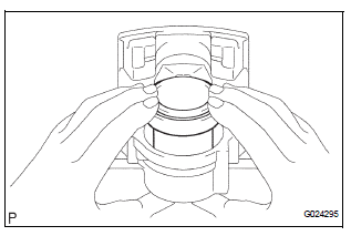
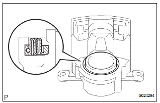
8. INSTALL CYLINDER BOOT
(a) Install a new cylinder boot to the rear disc brake cylinder sub-assembly.
NOTICE: Install the boot securely to the grooves of the cylinder and piston.

(b) Using a screwdriver, install the set ring.
9. INSTALL REAR DISC BRAKE BUSH DUST BOOT
(a) Install the 2 rear disc brake bush dust boot to the disc brake cylinder mounting LH.
10. INSTALL REAR DISC BRAKE CYLINDER SLIDE PIN
(a) Apply the lithium soap base glycol grease to the sealing surface of the 2 rear disc brake cylinder slide pins.
 Inspection
1. INSPECT BRAKE CYLINDER AND PISTON
(a) Check the brake cylinder bore and rear disc brake
piston for rust or scoring.
2. INSPECT PAD LINING THICKNESS
(a) Using a ruler, measure the pad lining ...
 Installation
HINT:
Install the RH side by the same procedure as the LH side.
1. INSTALL REAR DISC BRAKE CYLINDER MOUNTING
LH
(a) Install the rear disc brake cylinder mounting LH with
the 2 bolts.
Torque: 8 ...
Other materials:
Short to GND in Side Squib LH Circuit
DTC B0117/45 Short to GND in Side Squib LH Circuit
DESCRIPTION
The side squib LH circuit consists of the center airbag sensor assembly and
the front seat side airbag
assembly LH.
This circuit instructs the SRS to deploy when deployment conditions are met.
DTC B0117/45 is recorded when a s ...
Precaution
NOTICE:
When the ignition switch is turned off and the engine
temperature is high, the cooling fans may operate for
approximately 3 minutes.
After turning the ignition switch off, keep hands and
objects away from the fans when they are operating.
HINT:
If al ...
Mechanical system tests
1. PERFORM MECHANICAL SYSTEM TESTS
(a) Measure the stall speed.
The object of this test is to check the overall
performance of the transaxle and engine by
measuring the stall speeds in the D position.
NOTICE:
Driving test should be done on a paved road
(a nonskid road).
Per ...
