Toyota Sienna Service Manual: Speaker Circuit
DESCRIPTION
The sound signal that has been amplified by the stereo component amplifier is sent to the speakers from the stereo component amplifier through this circuit.
If there is a short in this circuit, the stereo component amplifier detects it and stops output to the speakers.
Thus sound cannot be heard from the speakers even if there is no malfunction in the stereo component amplifier or speakers.
When a short is detected in the speaker circuit, no sound can be heard from the speakers.
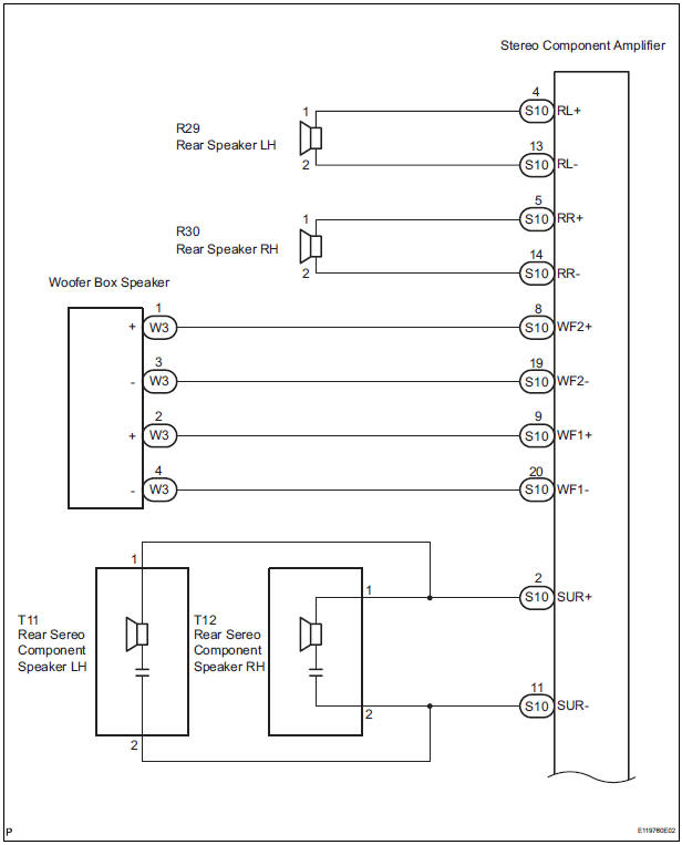
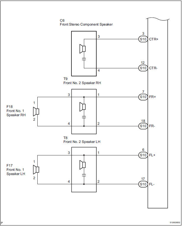
WIRING DIAGRAM
INSPECTION PROCEDURE
1 CHECK HARNESS AND CONNECTOR
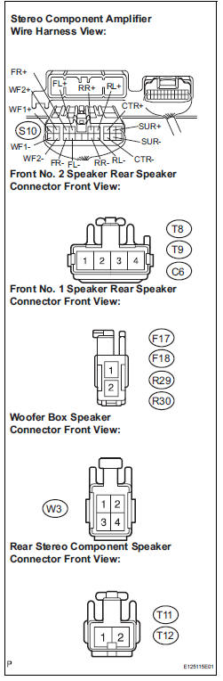
- Disconnect the connectors shown in the illustration on the left from the stereo component amplifier and speakers.
- Measure the resistance between the front No. 2
speakers and the stereo component amplifier to check
for an open circuit in the wire harness.
Standard resistance: Below 1 Ω
- Measure the resistance between rear speakers and the
stereo component amplifier to check for an open circuit
in the wire harness.
Standard resistance: Below 1 Ω
- Measure the resistance between the front stereo
component speaker and the stereo component amplifier
to check for an open circuit in the wire harness.
Standard resistance: Below 1 Ω
- Measure the resistance between the woofer box speaker
and the stereo component amplifier to check for an open
circuit in the wire harness.
Standard resistance: Below 1 Ω
- Measure the resistance between the front No. 1 speaker
and the front No. 2 speaker to check for an open circuit
in the wire harness.
Standard resistance: Below 1 Ω
- Measure the resistance between the rear stereo
component speaker and the stereo component amplifier
to check for an open circuit in the wire harness.
Standard resistance: Below 1 Ω
- Measure the resistance between each speaker and body
ground to check for a short circuit in the wire harness.
Standard resistance: 10 kΩ or higher
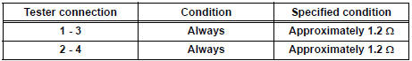
2 INSPECT WOOFER BOX SPEAKER
- Resistance check.
- Measure the resistance according to the value(s) in the table below.
NOTICE: The speaker should not be removed for checking.
Standard resistance
INSPECT FRONT NO. 1 SPEAKER
- Resistance check.
- Measure the resistance between the terminals of the speaker.
Standard resistance: 4 to 6 Ω
4 INSPECT FRONT NO. 2 SPEAKER
- Check that the malfunction disappears when another speaker in good condition is installed.
OK: Malfunction disappears.
HINT:
- Connect all the connectors to the front No. 2 speakers.
- When there is a possibility that either right or left front speaker is defective, inspect by interchanging the right one with the left one.
5 INSPECT REAR SPEAKER
- Resistance check.
- Measure the resistance between the terminals of the speaker.
Standard resistance: Approximately 2.6 Ω
6 INSPECT FRONT STEREO COMPONENT SPEAKER
- Resistance check.
- Measure the resistance between the terminals of the speaker.
Standard resistance: 1.2 to 2.2 Ω
7 INSPECT REAR STEREO COMPONENT SPEAKER
- Check that the malfunction disappears when another speaker in good condition is installed.
OK: Malfunction disappears.
HINT:
- Connect all the connectors to the rear stereo component speakers.
- When there is a possibility that either right or left front speaker is defective, inspect by interchanging the right one with the left one.
PROCEED TO NEXT CIRCUIT INSPECTION SHOWN IN PROBLEM SYMPTOMS TABLE
 Parking Brake Switch Circuit
DESCRIPTION
This circuit is from the parking brake switch to the radio and navigation
assembly.
WIRING DIAGRAM
INSPECTION PROCEDURE
1 CHECK BRAKE WARNING LIGHT
Check that the brake warni ...
 Sound Signal Circuit between Radio and Navigation Assembly and
Television Display Assembly
Sound Signal Circuit between Radio and Navigation Assembly and
Television Display Assembly
DESCRIPTION
The television display assembly sends an RSE sound signal to the radio and
navigation assembly through
this circuit. The sound signal that has been sent is amplified by the stereo
co ...
Other materials:
Front Occupant Classification Sensor RH Circuit
Malfunction
DTC B1781 Front Occupant Classification Sensor RH Circuit
Malfunction
DESCRIPTION
The front occupant classification sensor RH circuit consists of the occupant
classification ECU and the
front occupant classification sensor RH.
DTC B1781 is recorded when a malfunction is detected in the fron ...
Clearance Warning ECU Power Source Circuit
DESCRIPTION
This circuit provides power to the clearance warning ECU.
WIRING DIAGRAM
INSPECTION PROCEDURE
1 CHECK HARNESS AND CONNECTOR (CLEARANCE WARNING ECU - AIR CONDITIONER
AMPLIFIER)
Disconnect the connectors from the clearance warning
ECU C9 and air conditioner amplifier con ...
Speed sensor check (when using sst check wire)
(a) Check the speed sensor signal.
(1) Drive the vehicle straight forward. Drive the
vehicle at a speed of 45 km/h (28 mph) or higher
for several seconds and check that the ABS
warning light goes off.
HINT:
The signal check may not be completed if the
vehicle has its wheels spun or the stee ...
