Toyota Sienna Service Manual: Disassembly
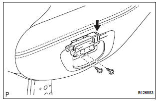
1. REMOVE REAR NO. 2 SEAT COVER BEZEL
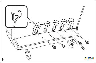
- Remove the 5 screws.
- Disengage the 5 claws and remove the rear No. 2 seat cover bezel.
2. REMOVE REAR SEAT RECLINING COVER LH
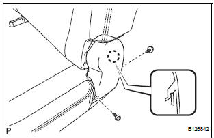
- Remove the 2 screws.
- Disengage the claw and remove the rear seat reclining cover LH.
3. REMOVE REAR SEAT RECLINING COVER RH
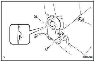
- Remove the 2 screws.
- Disengage the claw and remove the rear seat reclining cover RH.
4. REMOVE REAR SEAT HEADREST ASSEMBLY
5. REMOVE REAR NO. 2 SEAT HEADREST SUPPORT ASSEMBLY LH
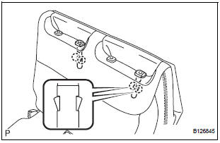
- Remove the 2 pads.
- Remove the 2 clips.
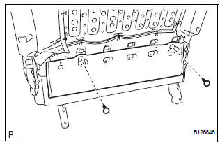
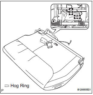
- Remove the 23 hog rings and disconnect the No. 2 seatback cover sub-assembly with pad.
- Turn back the No. 2 seatback cover sub-assembly.
- Disengage the 4 claws and remove both rear No. 2 seat headrest support assemblies LH.
6. REMOVE REAR NO. 2 SEAT HEADREST SUPPORT ASSEMBLY RH
HINT: Use the same procedure described for the LH side.
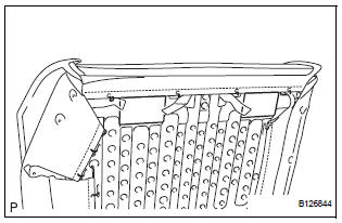
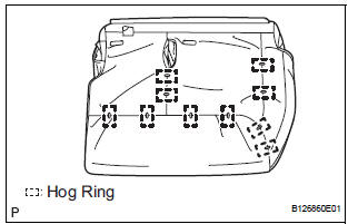
7. REMOVE NO. 2 SEATBACK COVER SUB-ASSEMBLY WITH PAD
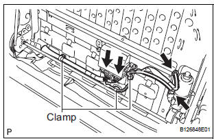
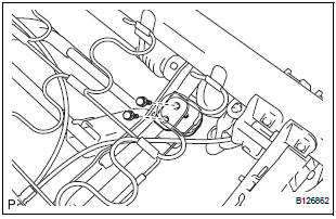
- Disconnect the connectors.
- Disengage the 3 clamps and remove the No. 2 seatback cover sub-assembly with pad.
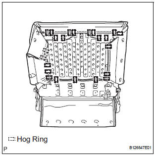
8. REMOVE NO. 2 SEATBACK COVER SUB-ASSEMBLY
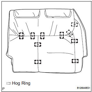
- Remove the 10 hog rings and No. 2 seatback cover sub-assembly.
9. REMOVE NO. 2 SEATBACK PAD
10. REMOVE FOLD SEAT CONTROL ECU
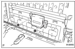
- Remove the 2 nuts and fold seat control ECU.
11. REMOVE NO. 2 SEATBACK FRAME SUB-ASSEMBLY
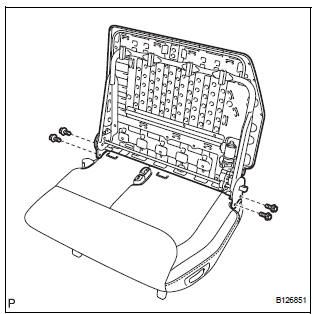
- Remove the 4 bolts and No. 2 seatback frame subassembly.
12. REMOVE RECLINING REMOTE CONTROL LEVER BEZEL
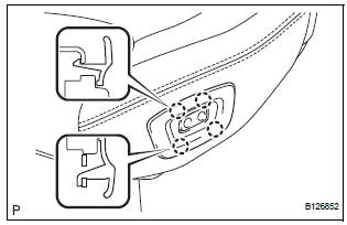
- Disengage the 4 claws and remove the reclining remote control lever bezel.
13. REMOVE REAR POWER SEAT SWITCH
- Remove the 2 screws.
- Disconnect the connector and remove the rear power seat switch.
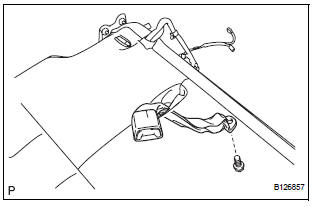
14. REMOVE REAR NO. 2 SEAT LAP BELT ASSEMBLY CENTER WITH INNER
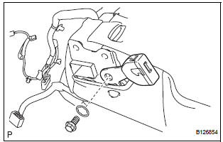
- Remove the bolt, washer and rear No. 2 seat lap belt assembly center with inner.
15. REMOVE REAR NO. 2 SEAT BELT ASSEMBLY INNER
- Remove the 2 hog rings.
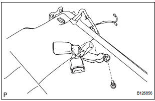
- Remove the bolt and rear No. 2 seat belt assembly inner.
16. REMOVE REAR SEAT BELT ASSEMBLY INNER
- Remove the bolt and rear seat belt assembly inner.
17. REMOVE REAR SEAT COVER
- Remove the 2 screws.
- Disengage the 2 claws and remove the rear seat cover.
18. REMOVE NO. 2 SEAT CUSHION COVER SUBASSEMBLY WITH PAD
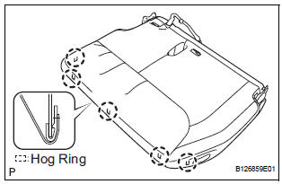
- Raise the 5 rear seat cushion edge protectors.
- Disengage the hooks and remove the No. 2 seat cushion cover sub-assembly with pad.
19. REMOVE NO. 2 SEAT CUSHION COVER SUBASSEMBLY
- Remove the 10 hog rings and No. 2 seat cushion cover sub-assembly.
20. REMOVE NO. 2 SEAT CUSHION PAD
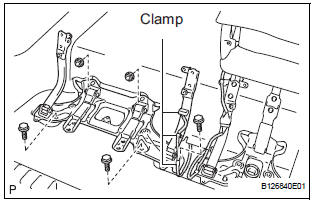
21. REMOVE REAR SEAT WIRE

- Disconnect the connector.
- Disengage the 3 clamps and remove the rear seat wire.
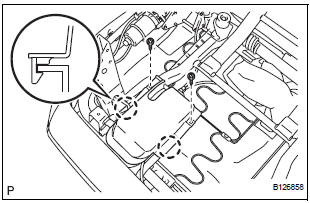
22. REMOVE NO. 2 SEAT CUSHION STOPPER
- Remove the 2 bolts and No. 2 seat cushion stopper.
HINT: Use the same procedure to remove the other stopper.
23. REMOVE NO. 2 SEAT CUSHION SPRING ASSEMBLY
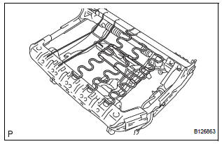
- Remove the No. 2 seat cushion spring assembly.
24. REMOVE NO. 2 SEAT CUSHION FRAME SUBASSEMBLY
25. REMOVE NO. 2 SEAT LEG SUB-ASSEMBLY
- Disengage the 3 clamps.
- Remove the 3 bolts, 2 nuts and No. 2 seat leg subassembly.
 Removal
1. DISCONNECT CABLE FROM NEGATIVE BATTERY
TERMINAL
2. REMOVE REAR NO. 2 SEAT LEG SIDE GARNISH SUB-ASSEMBLY
Disengage the 9 clips and remove the rear No. 2
seat leg side garnish sub-a ...
 Adjustment
HINT:
If the malfunction does not disappear by following the
procedure in ADJUSTMENT and the rear No. 2 seat
assembly needs to be replaced, do not disassemble the rear
No. 2 seat assembly.
1. ADJ ...
Other materials:
Terminals of ECU
1. TELEVISION CAMERA ASSEMBLY
Disconnect the T10 camera connector
Measure the voltage and resistance of each
terminal of the wire harness side connector.
If the result is not as specified, there may be a
malfunction on the wire harness side.
Reconnect the T10 ...
Side Airbag Sensor Assembly RH Circuit Malfunction
DTC B1140/32 Side Airbag Sensor Assembly RH Circuit Malfunction
DESCRIPTION
The side airbag sensor RH circuit consists of the center airbag sensor
assembly and side airbag sensor
RH.
If the center airbag sensor assembly receives signals from the side airbag
sensor RH, it judges whether or
...
Installation
1. INSTALL REAR DIFFERENTIAL SIDE GEAR SHAFT BOLT
(a) Install the bolt tightening the nut through the plate
washer.
2. INSTALL REAR DRIVE SHAFT ASSEMBLY LH
HINT:
(See page DS-26)
3. INSTALL REAR AXLE SHAFT NUT LH
HINT:
(See page DS-26)
4. INSTALL REAR SPEED SENSOR LH
HINT:
(See page D ...
