Toyota Sienna Service Manual: Removal
1. DISCONNECT CABLE FROM NEGATIVE BATTERY TERMINAL
2. REMOVE V-BANK COVER SUB-ASSEMBLY (See page EM-28)
3. REMOVE PURGE VSV
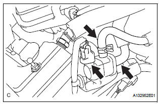
(a) Disconnect the purge VSV connector.
(b) Disconnect the 2 purge line hoses from the purge VSV.
(c) Remove the purge VSV from the air cleaner hose.
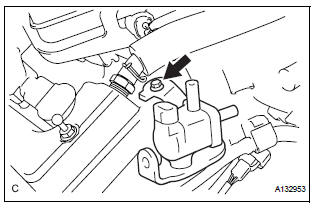
(d) Remove the bolt and No. 1 vacuum switching valve.
 Vacuum switching valve
Components
...
 Inspection
1. INSPECT PURGE VSV
(a) Measure the resistance of the purge VSV.
Standard resistance
If the result is not as specified, replace the purge
VSV.
(b) Check the operation of the purge VSV. ...
Other materials:
Refrigerant
On-vehicle inspection
1. INSPECT REFRIGERANT PRESSURE WITH MANIFOLD GAUGE SET
(a) This method uses a manifold gauge set to locate
problem areas. Read the manifold gauge pressure
when these conditions are established.
Test conditions:
Temperature at the air inlet is 30 to 35°C (86 to
95 ...
Short to GND in Rear Curtain Shield Squib RH
Circuit
DTC B1632/81 Short to GND in Rear Curtain Shield Squib RH
Circuit
DESCRIPTION
The rear curtain shield squib RH circuit consists of the center airbag sensor
assembly and the curtain
shield airbag assembly RH.
The circuit instructs the SRS to deploy when deployment conditions are met.
DTC ...
DTC check / clear
1. CHECK DTC
Prepare the intelligent tester.
Connect the intelligent tester to DLC3.
Turn the ignition switch to the ON position and turn
the intelligent tester main switch ON.
Use the intelligent tester to check the DTCs, and
note them down (For operating instructions, see the
int ...
