Toyota Sienna Service Manual: Vacuum switching valve
Components
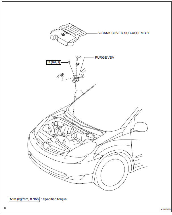
 Installation
1. INSTALL CHARCOAL CANISTER ASSEMBLY
(a) Install the 3 bolts and charcoal canister.
Torque: 29 N*m (296 kgf*cm, 21 ft.*lbf)
(b) Connect the purge line hose to the charcoal
canister.
(c) ...
 Removal
1. DISCONNECT CABLE FROM NEGATIVE BATTERY
TERMINAL
2. REMOVE V-BANK COVER SUB-ASSEMBLY (See
page EM-28)
3. REMOVE PURGE VSV
(a) Disconnect the purge VSV connector.
(b) Disconnect the 2 pur ...
Other materials:
Communication Error of Yaw Rate Sensor
DTC U0123 Communication Error of Yaw Rate Sensor
DESCRIPTION
This circuit detects the yaw rate of the vehicle and transmits its signal to
the skid control ECU and
distance control ECU.
DTC No.
DTC Detection Condition
Trouble Area
U0123
While the dynamic ...
Fail-safe chart
1. FAIL-SAFE FUNCTION
When communication fails in any of the main wires
(communication lines) due to a short circuit or other
causes, the fail-safe function, which is specified for
each system, operates to prevent the system from
malfunctioning.
The table below shows the effects on eac ...
Back Door Closer Switch Malfunction
DTC B2215 Back Door Closer Switch Malfunction
DESCRIPTION
This DTC is output when a malfunction occurs in the position switch in the
back door. This position switch
detects if the back door is in the latch position and sends a position signal to
the power back door ECU.
DTC No.
...
